
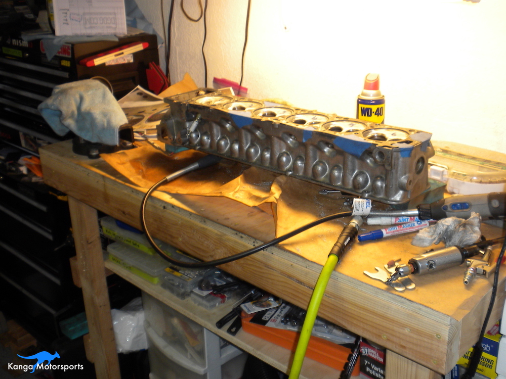
After I found out my old Datsun engine was a little tired, it was time to look into building a new motor. Building a new motor provides an opportunity for more power. Key to increasing the performance of an L-Series motor are modifications to the cylinder head. Components to modify include the valve train, intake/exhaust ports and also the cylinder chambers themselves. In the previous article we finished cleaning and inspecting the cylinder head.
Tools and Equipment Needed:
Old Intake and Exhaust Valves (Ground Down)
Old Used Spark Plug
Grease
Clear Plastic with Air Vents
Water
Paper Towels
Simple Green
Measuring Syringes (accurate to 0.1 CC or lower)
Note Paper and Pen
Air Compressor
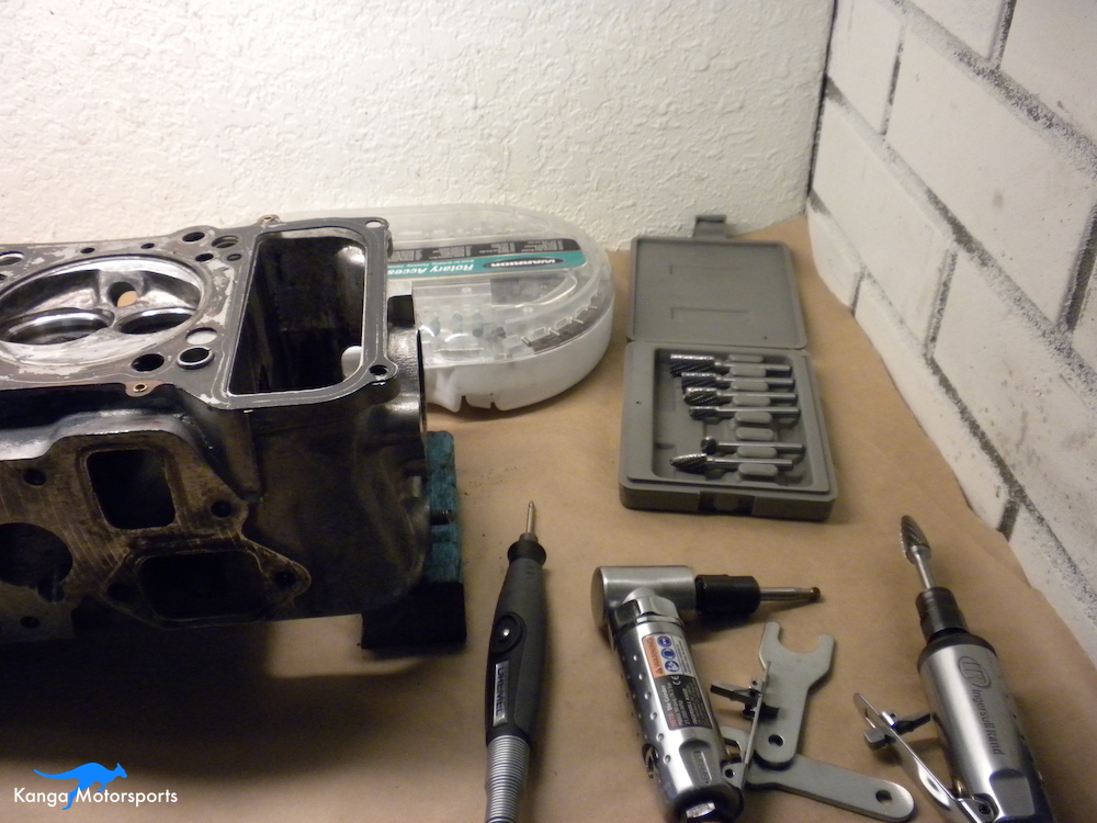
Straight Die Grinders - Ingersoll Rand 307B
90 Degree Die Grinders - Ingersoll Rand 301B
1/4 inch Carbide Burrs (Astro 2181 Double Cut Carbide Burr Set)
1/4 inch Shanks
80 and 120 Grit Sanding Scrolls (Harbor Freight PN: 62394)
Dremel with Flex Shaft
80 Grit Thin and Thick Flap Wheels (Dremel PN: 502 and 504)
120 Grit Thin and Thick Flap Wheels (Dremel PN: 503 and 505)
180 (dark brown) and 280 (light brown) Grit Finishing Buffs (Dremel PN: 511E)
320 Grit Finishing Buff (Dremel PN: 512E)
3/4 inch 3M Radial Bristle Discs
Blue 400 grit
Pink 600 grit
3M Radial Bristle Discs Mandrels
1/3 inch Felt Polishing Wheels (Dremel PN: 414)
White Rouge
Knife
Microfiber Towel
Tap Magic or WD40
HD Pro Simple Green
Old Head Gasket
Head Gasket Dowels (Nissan PN: 11053-73400)
Measuring Calipers
Machinist Dye or Sharpies
Scribe
Painters Tape
Paint Pen
Used Old Intake and Exhaust Valves
Grinder and Grinding Discs
Safety Goggles
Particle Filter Respirator Mask
Gloves
Cylinder Chamber Modifications:
Lets talk cylinder chambers. Extreme modifications include welding the chambers to provide larger quench areas or completely modify the geometry. We won't be doing that here. However, there are simpler modifications to the chambers that can provide improved performance:
Balancing the Chambers
Valve Unshrouding
Smoothing the Valve Seat Transitions
Polishing the Chambers
Grinding and sanding will produce a lot of fine metallic particles and dust, make sure you have proper safety equipment; safety goggles, gloves and a particle filter respirator mask.
Balancing the Chambers
You want the volume in all the chambers to be the same within +/-0.25 Cubic Centimeters (CCs). Start by measuring and recording the volume of each combustion chamber. Once you know these volumes you can determine which chambers need more or less material removed.
Clean the combustion chambers with simple green and paper towels.
Grease the seats of the valves to provide a water proof barrier, use the minimum amount of grease possible.
Place a bead of grease around the circumference of the combustion chamber.
Install an old used spark plug.
Lower the clear plastic with vent holes over the combustion chamber ensuring there is a water tight seal.
Using syringes measure out the water as you fill out the combustion chamber. Record the amount of water used. The air bubbles should go out of the vent holes. If you are having trouble with air bubbles you might need additional vent holes.

Remove the plastic and drain out the water. Clean off any grease from the chamber and plastic using simple green and paper towels.
Repeat for each combustion chamber recording the volume as you go. It might take you a few goes to get repeatable and accurate measurements. Try it a few times until you get the hang of it.
You will need to repeat Combustion Chamber CC'ing throughout the process at each step as you remove material.
Valve Unshrouding
The side of the chamber and the edges of the intake and exhaust are close together. Providing extra clearance on the outside of the valves can increase the flow numbers and potentially more horsepower.
The process of removing material to provide additional clearance between the valve and the chamber is referred to as valve unshrouding.
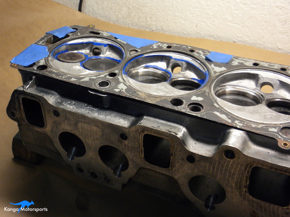
Insert the locating dowels into the head.
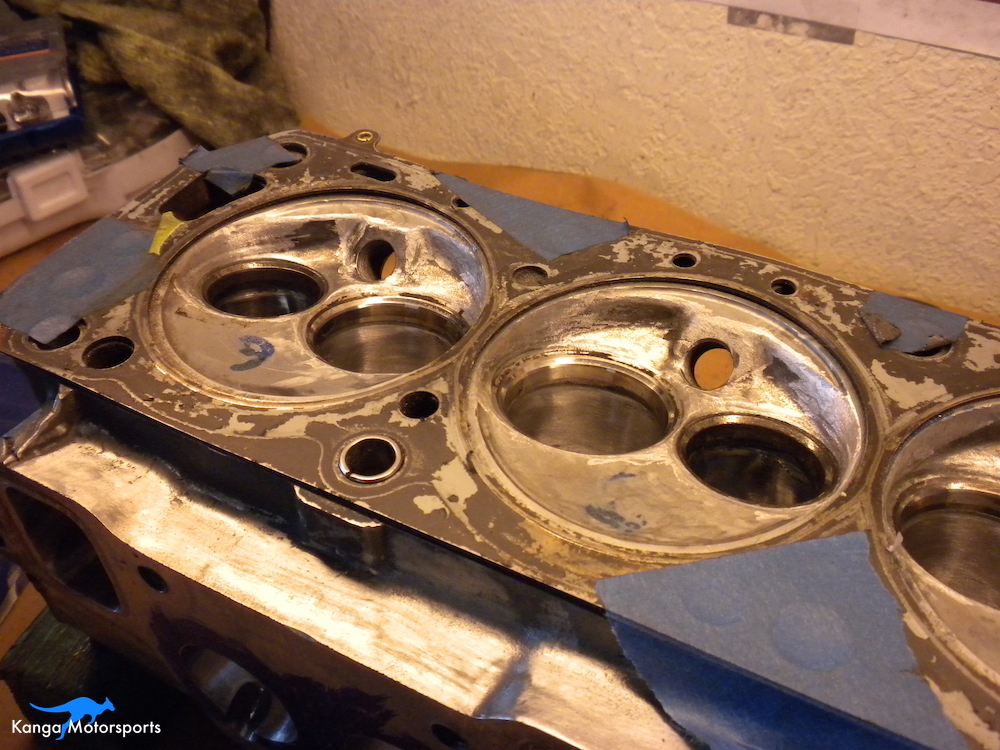
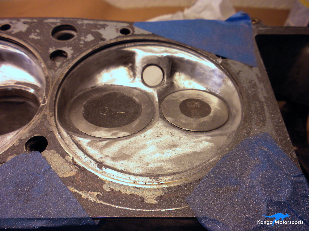
Paint machinist dye on the circumference of the cylinder chambers.
Place the old used head gasket over the head deck. You must use the same size head gasket as you plan to use in the build. No point putting a bigger or smaller gasket as you won't get the right size. Also you want to know your planned bore size before you start. You don't want to make the chamber size bigger than the bore.
With the gasket in place use the scribe to mark the gasket limit. This is the maximum size. Do not go bigger as you will under cut the gasket.
Check this line against you bore size, do not go bigger than the bore which might be less than the gasket.
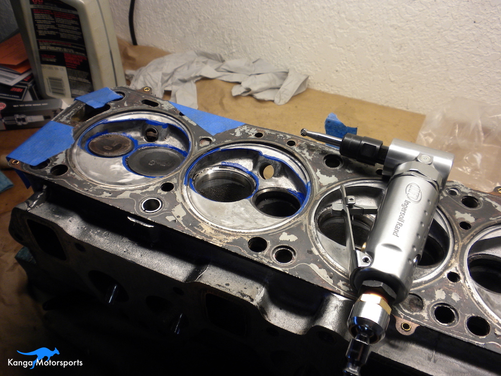
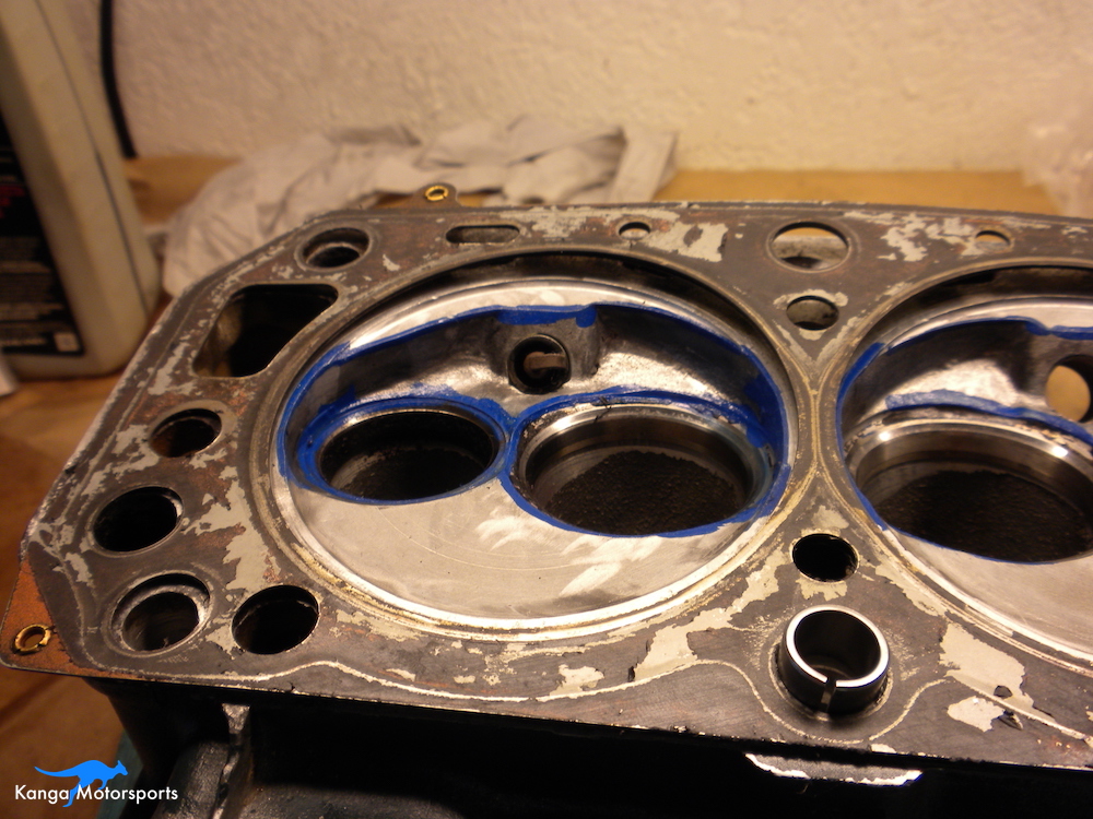
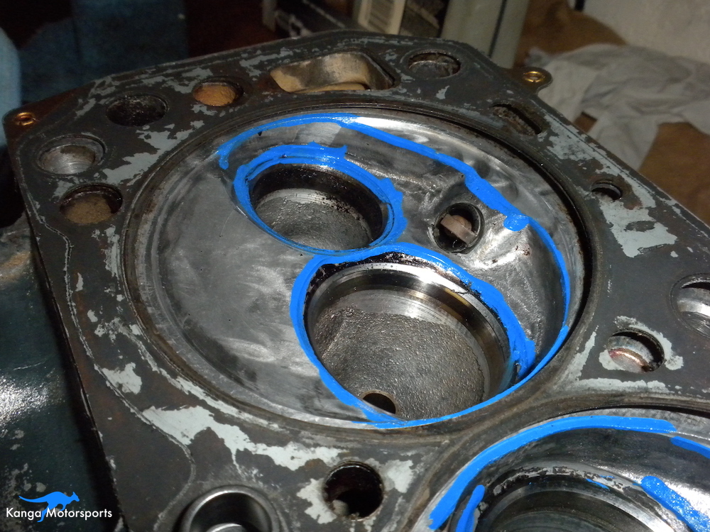
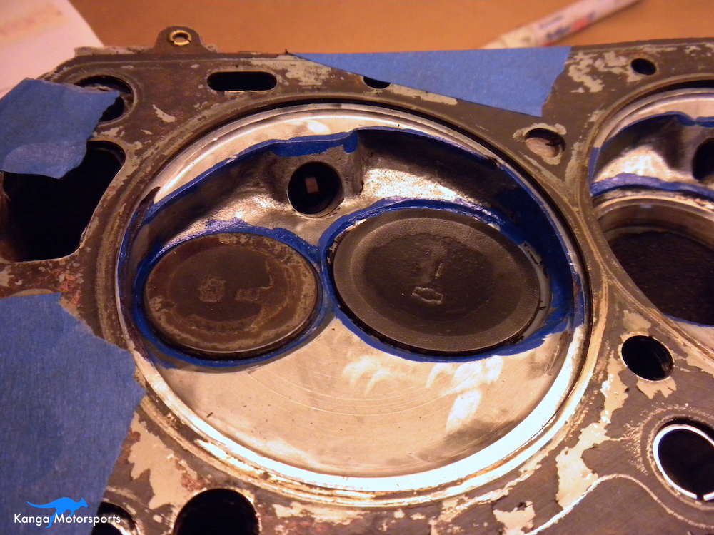
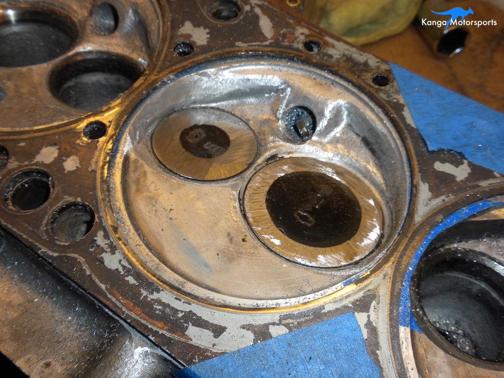
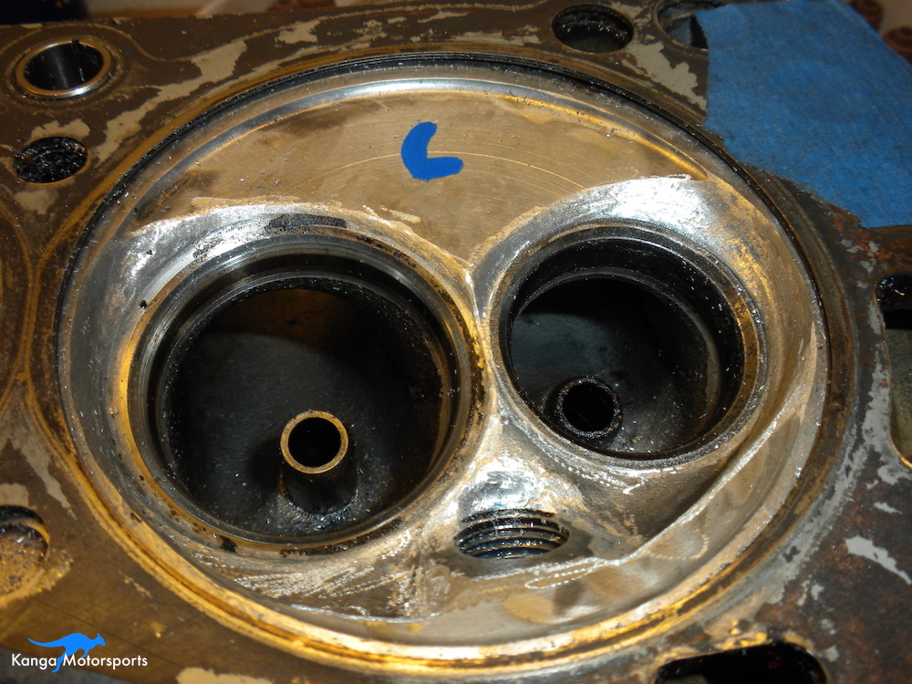
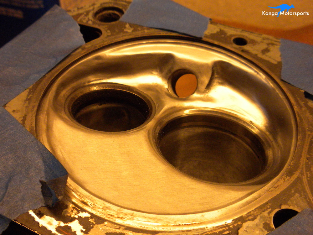
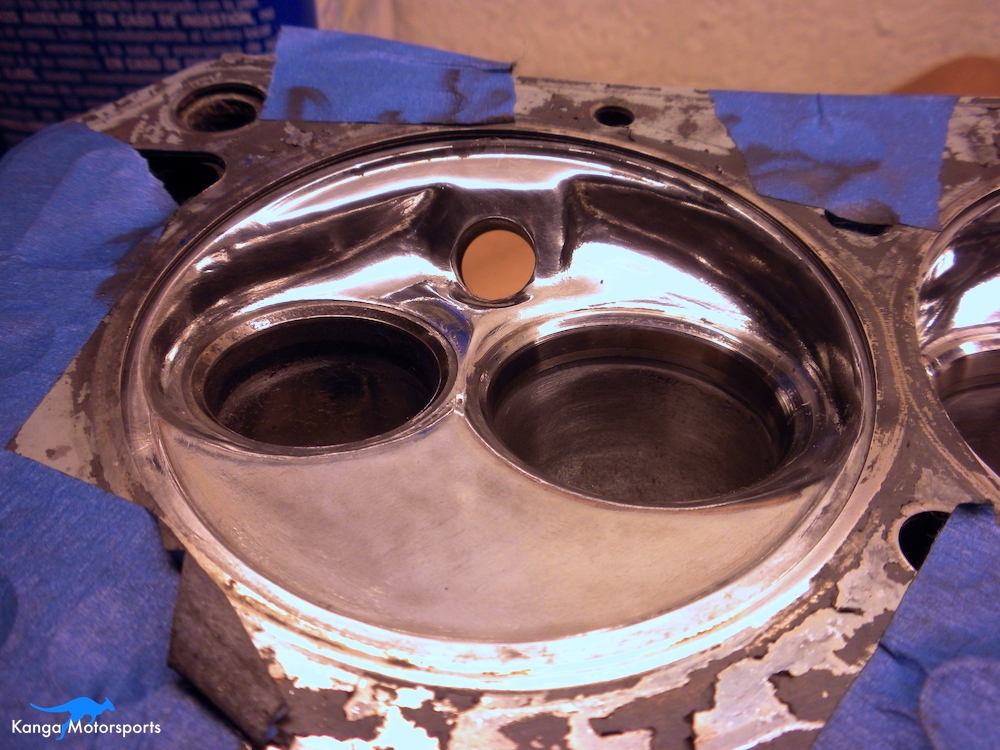
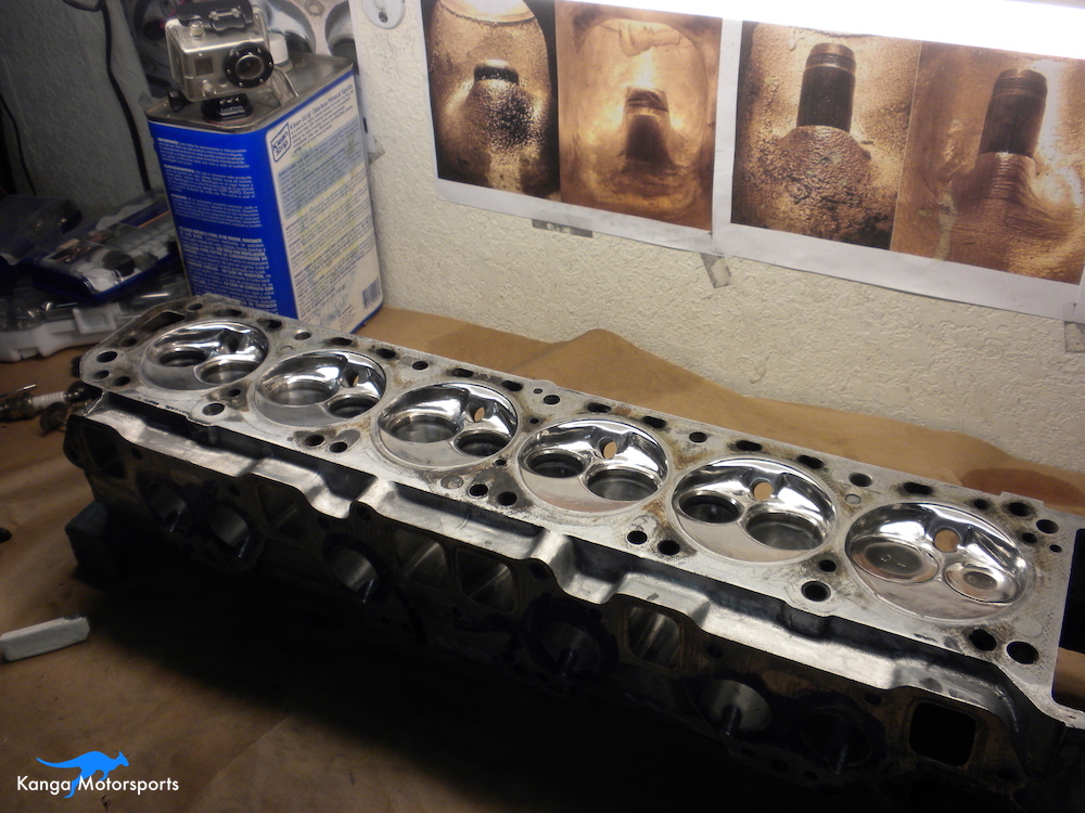
Before you start, mark the areas you want to remove with a paint pen. I started using white but it became hard to see when the metal chips and dust was flowing. I switched to blue.
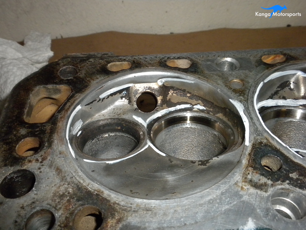
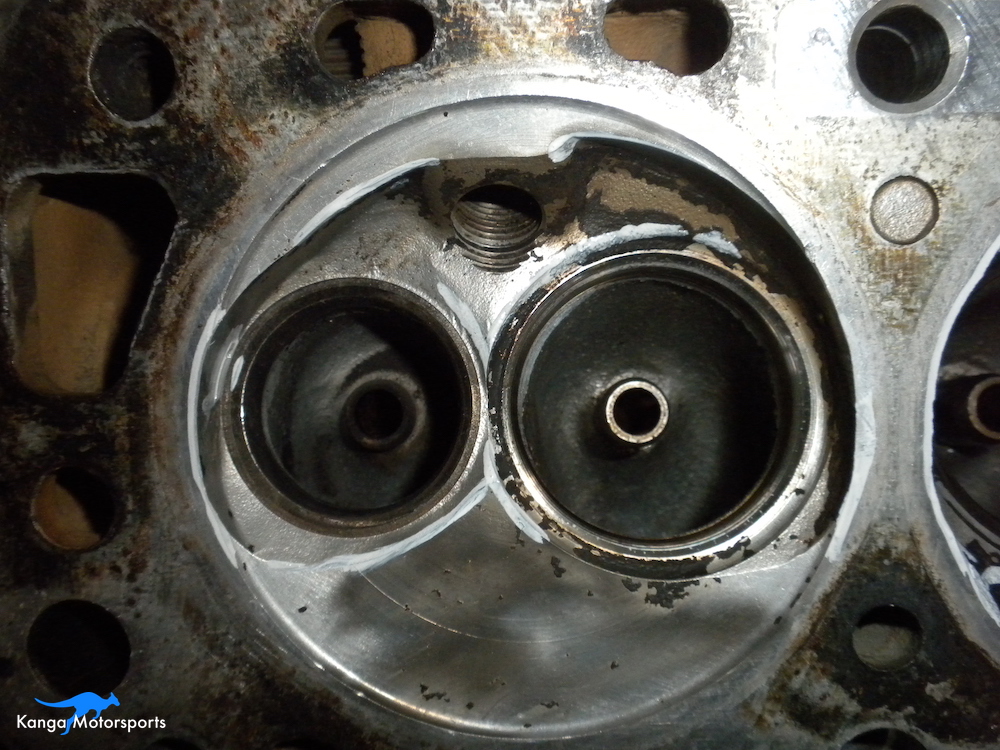
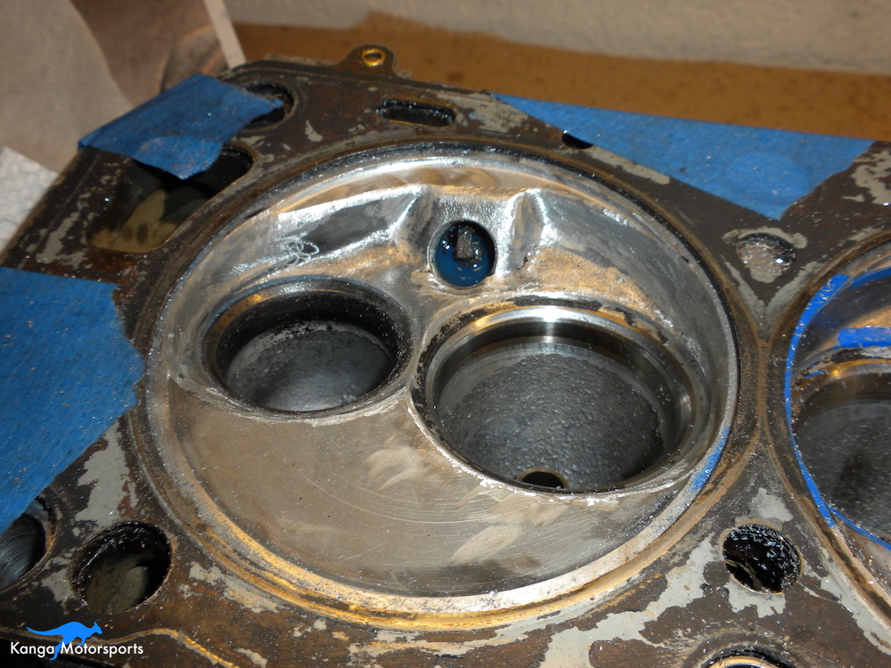
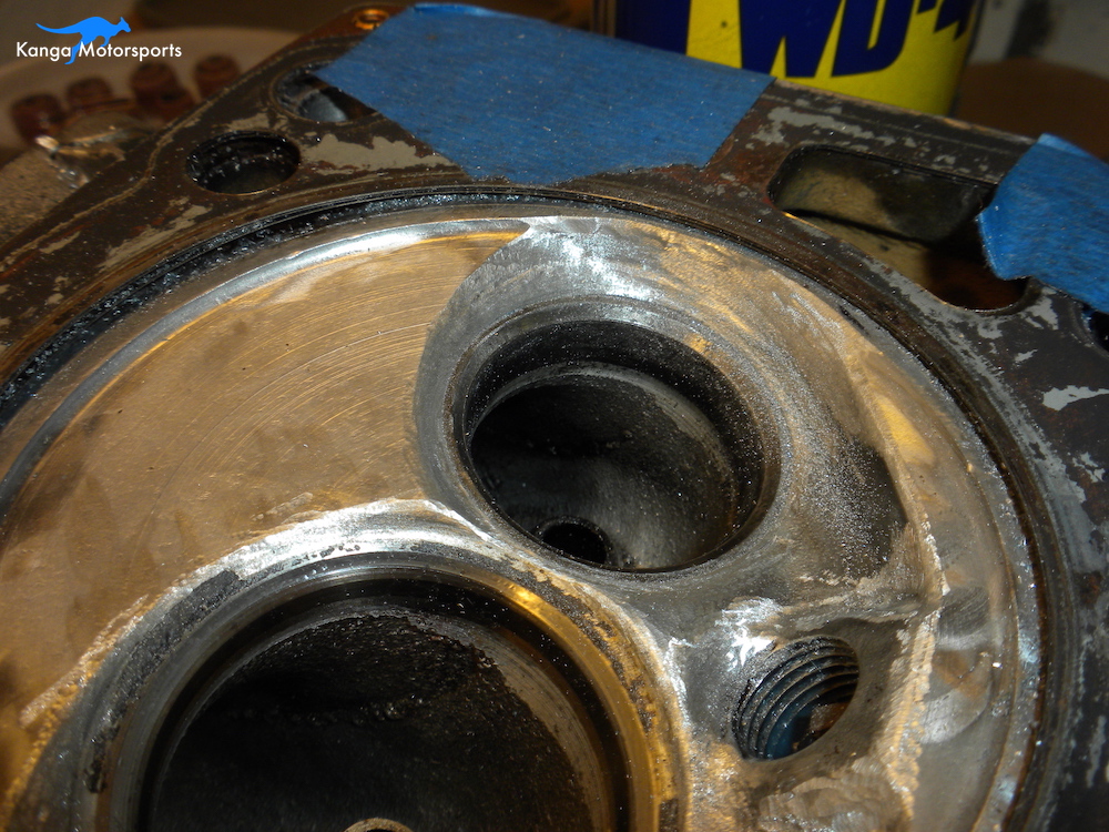
You can see in the images that there are also lots of discontinuities, steps or poorly meeting transitions. Common issues include edges from valve machining to the chamber wall, steps from the valve seat to the chamber floor and potential hot spots such as unused threads for the spark plugs.
You don't want to make the chamber as big as possible. You are trying to improve the flow around the valves and smooth out the transitions. Keep the chamber volume as small as possible. Large increases in volume are going to reduce your compression ratio.
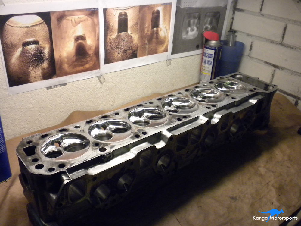
The other goal here is to make sure all the chambers have the same volume. For each grit, I start with one chamber and work on it until I am happy. Then I work down the line and make all of them the same.
To protect the valve seats, I use old valves and grind them down. Valve heads have a thickness to them that can provide access issues. Use a grinder to provide more clearance for the tools to access the pockets but still cover the valve seats. I also use an old spark plug to protect only the threads I need.
I use two different die grinders, one is straight the other is a 90 degree unit. Access and the area being worked determines which one to use based on control, reach and comfort.
The die grinder and carbide burr can skip or runaway on you. Position your hand to minimize any runaway. Use your other hand to help support the tool hand and hold it steady. You will have to reposition yourself and the head several times to be in the right orientation and work in the needed direction for the tool.
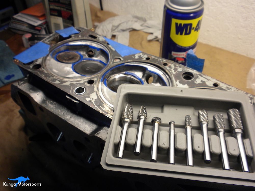
Cutting fluid like Tap Magic can prolong the life of cutting tools and also make the cuts easier. Sometimes the tool will skip if you are not at the right angle or moving in the wrong direct the cutting fluid also seems to give you a little more leeway.
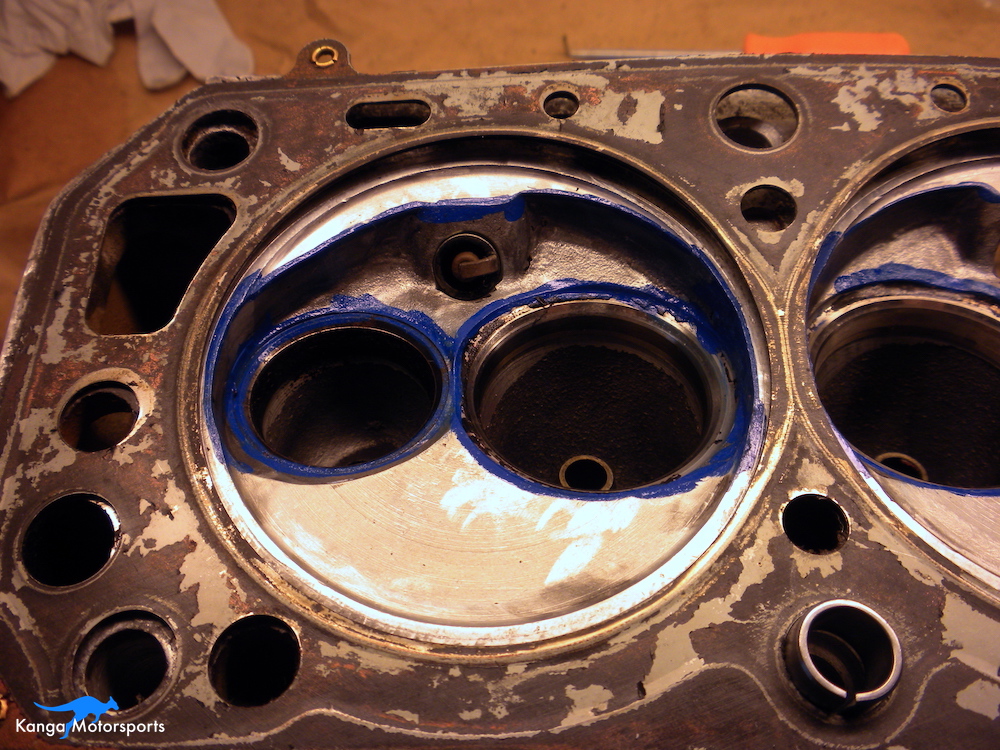
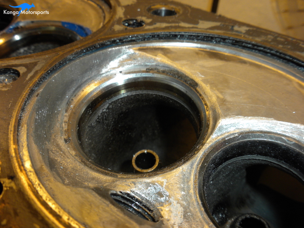
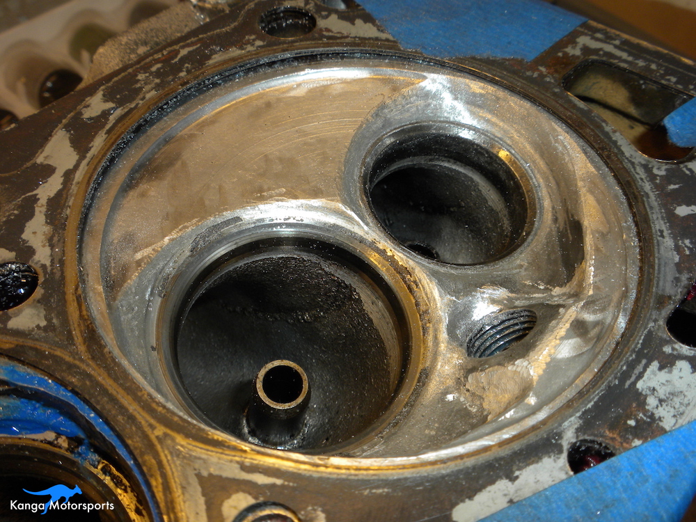
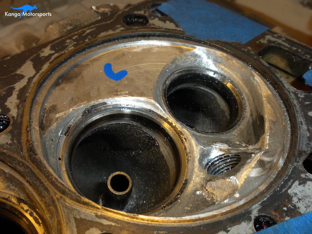
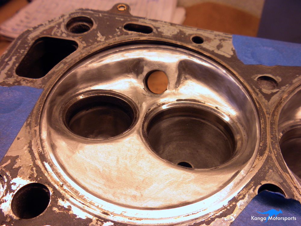
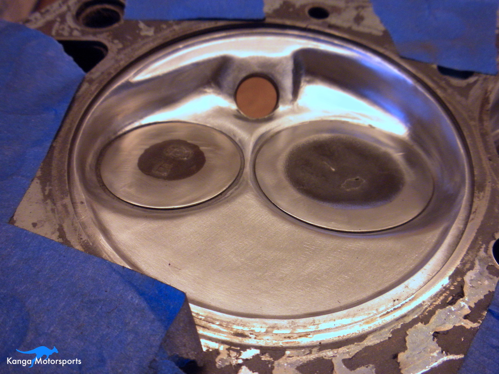
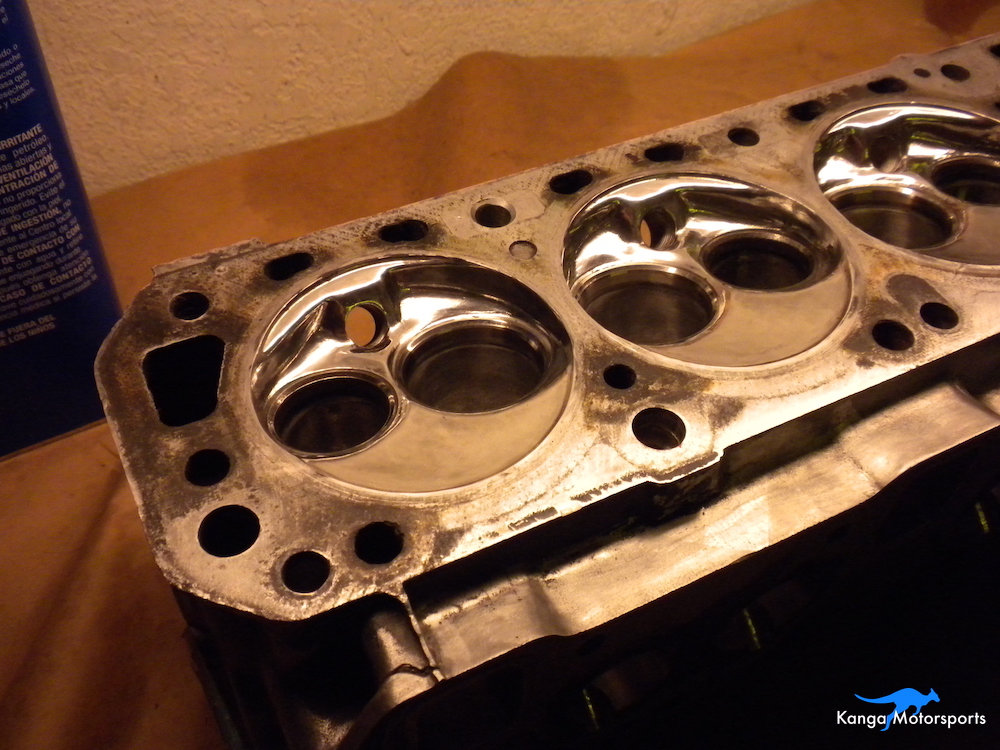
Don't just straight cut away all the material from the edge of the chamber next to the valve. You want there to be a nice radius and transition from valve seat, to the chamber floor and all the way up to the chamber wall. As the transition meets the other contours of the chamber you want to smooth these transitions to allow the air to flow. Don't completely destroy the features of the chamber and just hog it all out. These features are there for a reason.
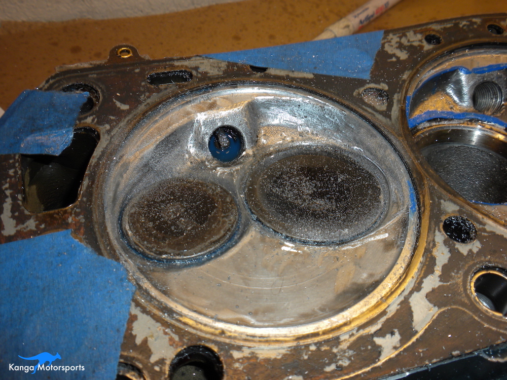
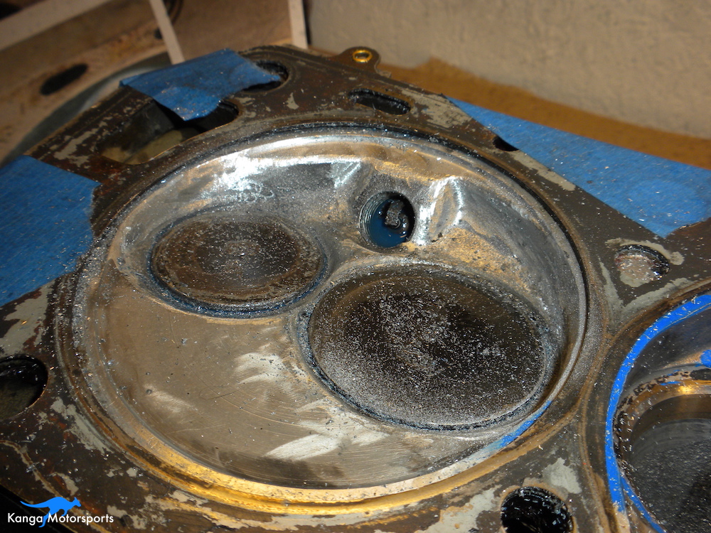
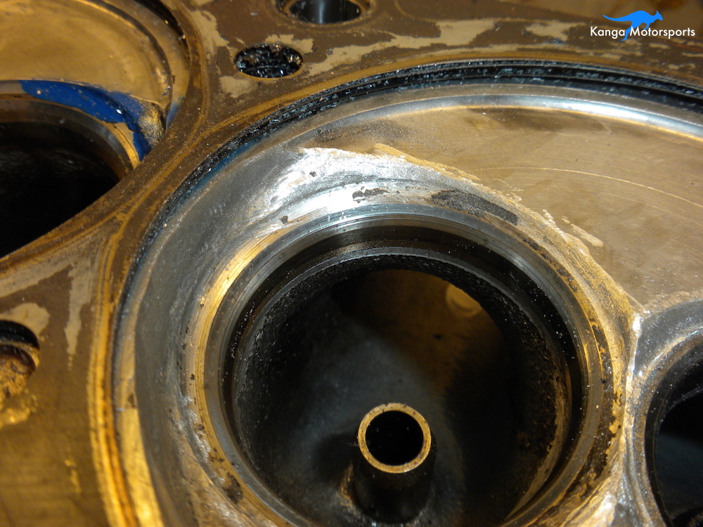
Be careful not to remove too much material using the carbides. You want to leave material to remove with future passes of the sanding flap wheels and finishing buffs. You can see the steps of the process in the images. Note how the cuts provide more area for the valves to flow and also smooth out the transitions.
The valve unshrouding still requires more smoothing with successive grits and final polishing. The process is the same as smoothing the valve seat transitions just applied to these specific areas. We discuss this further in the valve seat transition section.
Smoothing the Valve Seat Transitions
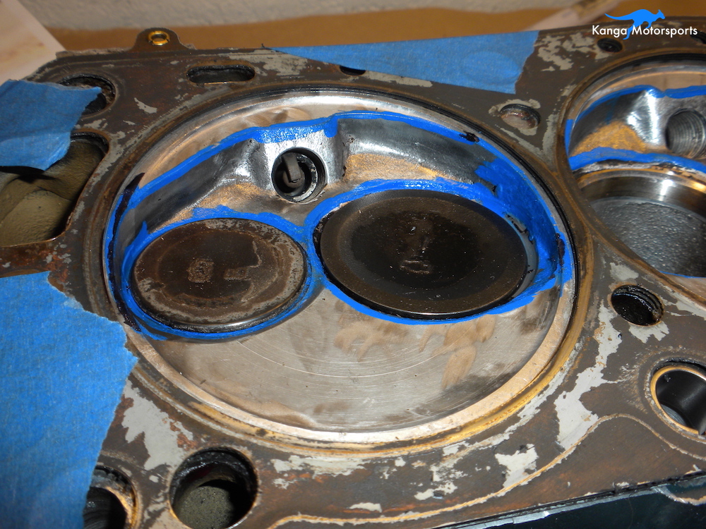
With the chambers CC'd and course cutting done with carbide burrs now it is time to do the fine shaping and try to match the volume in each chamber. Use an old head gasket to protect the deck surface. Use the old ground down valves to allow access to the edges but still protect the valve seat. You want to blend the transitions to the valve seat and any of the valve unshrouding that you performed with the carbide burrs.
The goal for this section is to remove any steps and sharp edges from the valve seats into the chamber. These issues can impact the flow of air into the chamber or create hot spots that cause pre-ignition.
The N42 doesn't have a quench pad like later model heads but you don't want to increase the chamber volume too much. Don't knock down the entire flat portion of the chamber.
The carbide burrs provide the rough cut and shape to the chamber. They were used to transition the valve seats, unshroud the valves, remove addition spark plug threads and smooth out rough areas from the factory machining.
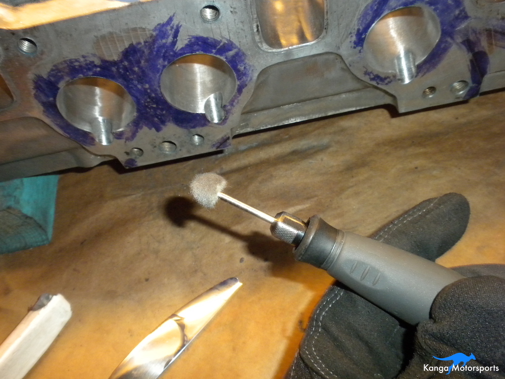
Yes you can use a Dremel but they really are not designed for it, they are low torque motors that operate at higher speeds. You want high torque motors at variable lower to medium speeds. I burned up at least one Dremel and the second one is on it's way out. Buy a dedicated high torque flex drive motor, they are a little more expensive but will outlast a Dremel.
Use the 80 grit flap wheels, I use two different sizes. A thin wheel is great of the pockets and reaching in tight spaces. A thicker wheel is better for overall smoothing and ensuring consistency over larger areas. Where possible you want to work in two perpendicular directions to provide a smoother and overall better finish. In some of the hard to reach spaces you can't always work in two directions but do the best you can.
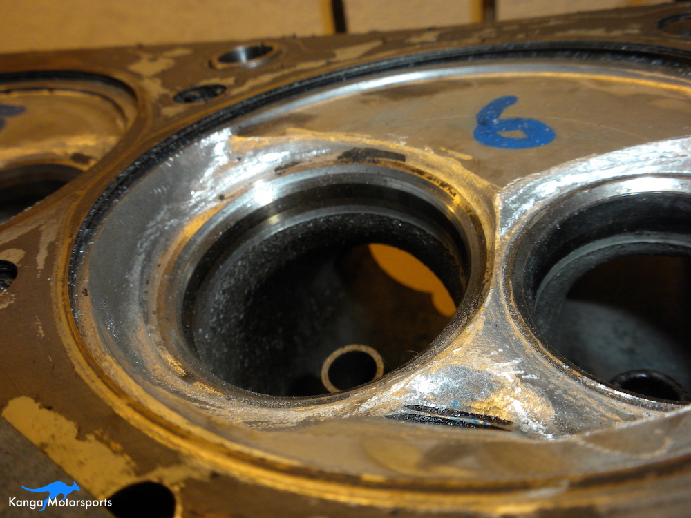
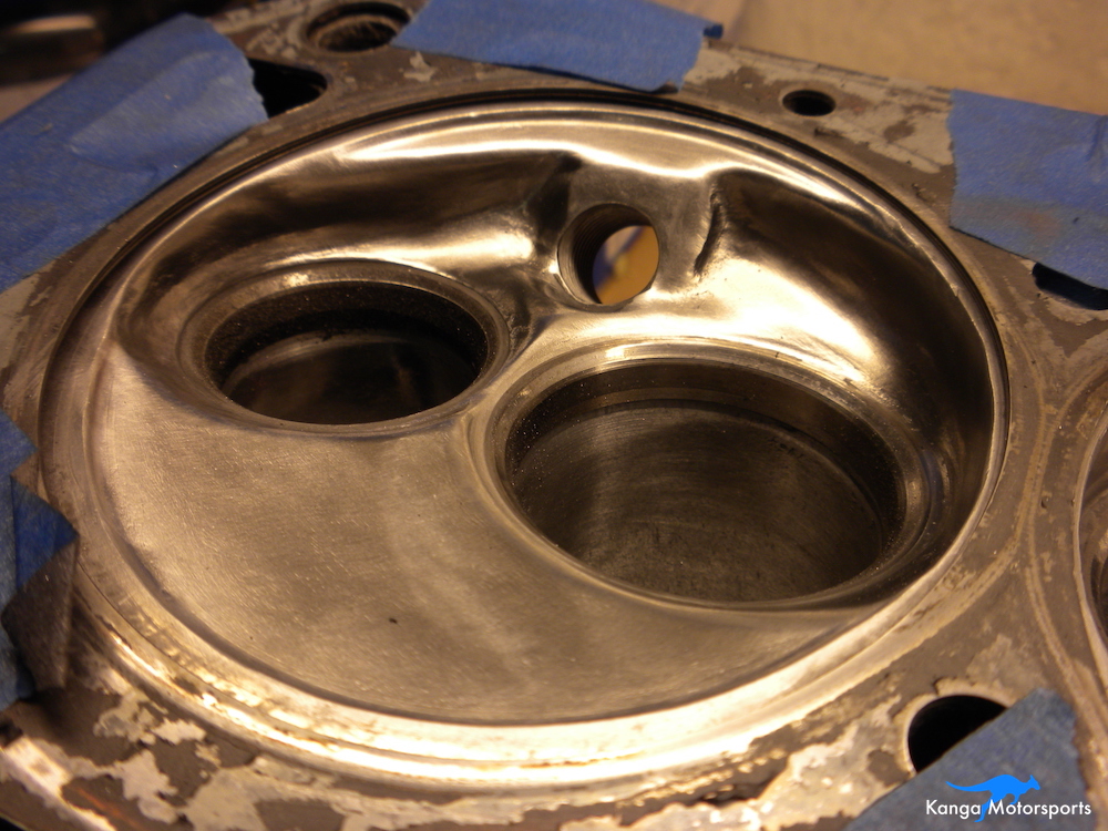
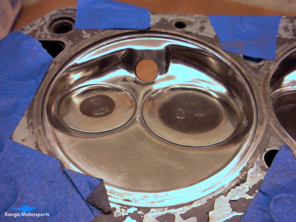
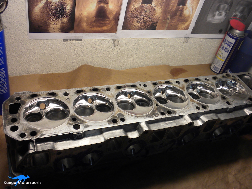
After the 80 grit the chamber should look a lot more defined and smoother. The rough cuts and chips from the carbide burrs should all be gone. The deep and fine scratches should be gone as well. The surface will look shiny and smooth but very dull. It will get smoother and shinier with successive grits.
Before you move to the 120 grit you want to repeat you CC measurements of each chamber. Each chamber should be matched to the others within 0.25 cc. Record the values as you go. It shouldn't matter but I switched out the ground down valves to some normal used valves when cc'ing that way I could calculate the compression ratio more accurately using the final volume. There will likely be a few chambers that need further attention. Go back over these chambers with the 80 grit flap wheels and repeat your CC measurements until they are matching.
Next use the 120 grit flap wheels both thin and thick. Again work in two perpendicular directions removing all the fine scratches. When complete with all 6 combustion chambers remeasure the volumes. They should now be within 0.25 cc. If they are not go back and touch up the necessary chambers with the 120 grit flap wheels.
With the chambers matched you can now begin the finishing process prior to polishing. The steps used are 180 grit buff, 280 grit buff and 320 grit buff. On each grit make sure the fine scratches are gone before proceeding to the next grit. Make two passes perpendicular to each other to remove the fine scratches from the last grit. Don't be afraid of going back a grit if the fine scratches are not reduced at the next step.
The good thing about the finishing buffs is that they can conform to the different shapes in the chamber. Don't press too hard with the buffs as they will wear out very quickly. Experiment with pressure and you will get the hang of it. I used 2-3 buffs at each grit to do all 6 chambers. The chambers should look brighter and shinier with each increase in grit.
Polishing the Chambers
With the chamber shaping complete, CC them again to make sure they are matched. If they are not matched do some final shaping. You should only have to remove very little material to get them matched at this point. Once they are matched within 0.25 CC you can proceed to polishing.
Use the ground down valves to protect the valve seats.
Before pulling out the polishing wheels and white rouge you want to remove the fine scratches. There are a variety of different ways to do this including finer buffs. I found that 3M radial bristle discs work really well and don't leave a lot mess behind.
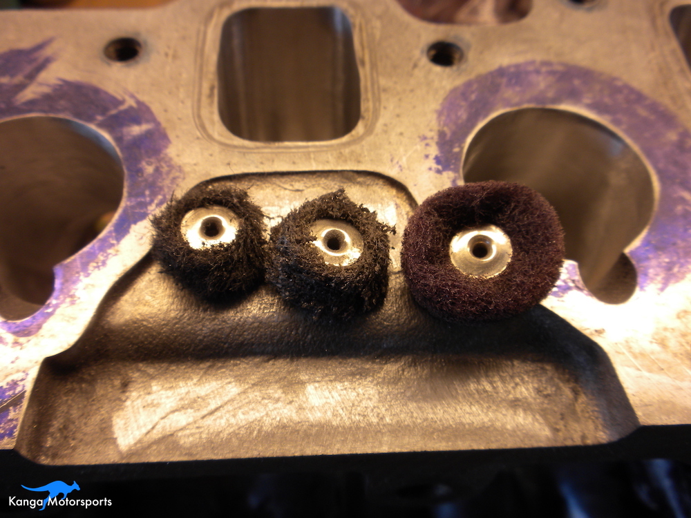
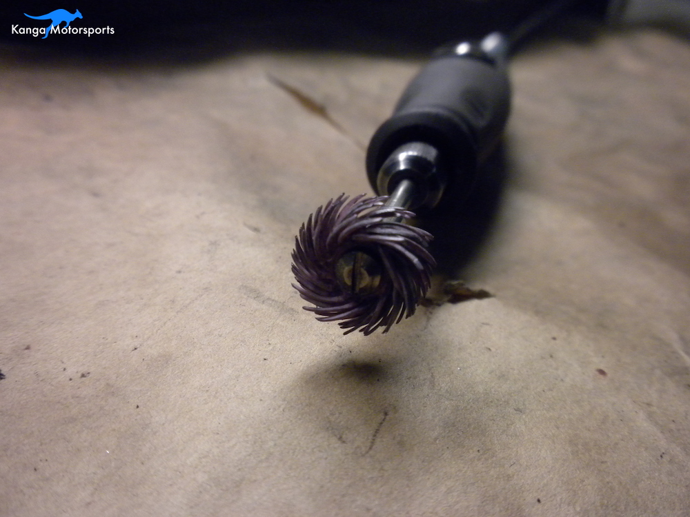
I used 3M radial bristle discs as Dremel doesn't make 400 and 600 grit buffs and with the chamber shapes it was difficult to wet sand. The 3M radial bristle discs are small so not good for large areas but perfect for chambers and ports. I use the Blue (400 grit) followed by the pink (600 grit). Use a minimum of 3 discs on a mandrel driven by a flex drive motor or Dremel with flex shaft.
The good thing with the bristle discs is they can get into the small radii and conform to the combustion chamber shapes. Just like with the sanding buffs, make sure the fine scratches are gone before proceeding to the next grit. Make two passes perpendicular to each other to remove the fine scratches from the last grit and get the shiny finish.
For polishing you can continue to use the various grades of 3M bristle discs but I found the small polishing felt wheels with white rough worked very well after the 600 grit.
A knife can be used to remove build up on the felt wheels and cut a new surface into the felt. During and after polishing use a microfiber towel to remove any excess polishing compound.
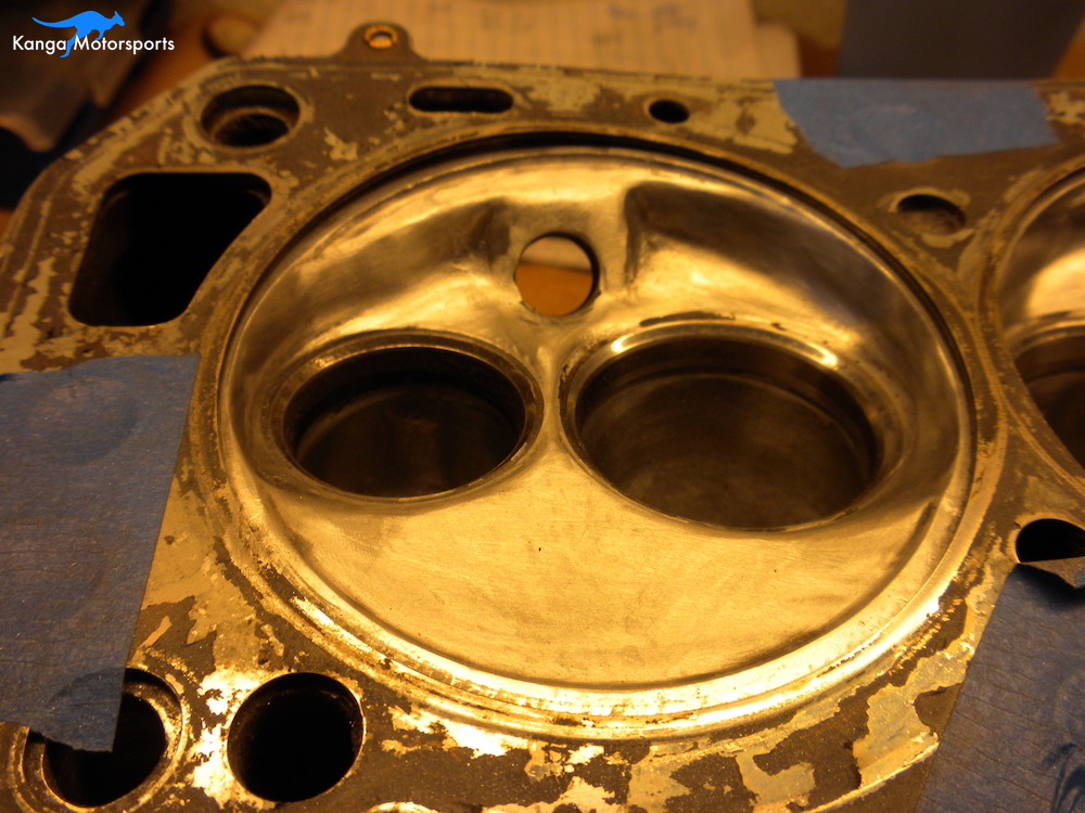
Once you are finished polishing your chambers should be all shiny. If you still have minor scratches that you are unhappy with go back and remove them with highest grit possible. Make sure you are happy with the finish for the grit you have before moving on to the next grit. Polishing takes time don't rush it.
In the next article in the engine build series we further modify the cylinder head working on the intake and exhaust ports.
Want more articles on our Datsun Engine Build sign up for our Monthly Newsletter.
Other Datsun Engine Build Articles


