In the previous article we finished up the cylinder head work by matching the intake ports. Before you can start modifying the engine block you need to know what you have. During the disassembly process you can measure all the parts of the engine and compare them to the Nissan specifications. Note it all down and then you will able to determine what work needs to be done at the machine shop.

Tools and Equipment Needed:
Magnetic Parts Tray
Ziplock Bags and a Sharpie
Masking Tape
Rubber Caps
Rubber Mallet
Hammer
Screwdriver
Channellocks or Vise Grips
Breaker Bar
10mm, 12mm, 14mm and 17mm Socket and Ratchet
Engine Stand - Harbor Freight PN: 69520
Four M10 x 1.5 x 70mm Engine Stand Bolts
M10 Washers
Engine Hoist - Harbor Freight PN: 69512
Lifting Equipment
Dial Gauge accurate to 0.0001 inch
Magnetic Stand - Harbor Freight PN: 5645
1-2, 2-3 and 3-4 inch micrometer accurate to 0.0001 inch
1-2, 2-3 and 3-4 inch bore gauge accurate to 0.0001 inch
24 inch Straight Edge
Feeler Gauges
40 ft-lbs (5.5 kg.m) Torque Wrench
Small 2 x 4 Block of Wood
Bench Vise
Rags
Pry Bar
Razor Blade
Gasket Scrapper - TEKTON 5876
Oil Drain Pan
2kg scale accurate to 0.1 grams
Spring Loaded Center Punch
Nissan Factory Service Manual - EM Engine Mechanical
Digital Camera
Engine Disassembly:
I picked up an F54 block that was stuck not the best buy but the the price was right and it didn't look in too bad condition. Even if all I could use was the internal components then I would still come out ahead. The crank was stuck and the block wouldn't turn over. So it was time to disassemble and work out what was wrong.
Download the Nissan Factory Service Manual for the year of your block. You can find many of the Z car manuals here. The subsection you want is EM-Engine Mechanical. The manual should have the all the factory specification and sizes that need to be checked.
If you haven't already drain the coolant and engine oil out of the block. Dispose of both appropriately. Likely there will be some residual fluids left when you are taking it apart. You will want to have some rags handy to clean up any mess. Guess how I learned this.
I had the motor on a dolly so I could move it around the garage before putting it onto an engine stand. The dolly also takes up less space than an engine stand. To disassemble the motor start by removing the water pump. There are 6 bolts use a 10mm for the two smaller bolts and a 12mm socket and ratchet for the larger and longer bolts.
Next remove the oil pump. It is connected via 4 bolts that can be removed using a 12mm socket and ratchet. It should just slide out the bottom. Bag and tag all the parts. I use ziplock bags and masking tape on the threaded ends of the bolts to keep everything together and in the right holes.
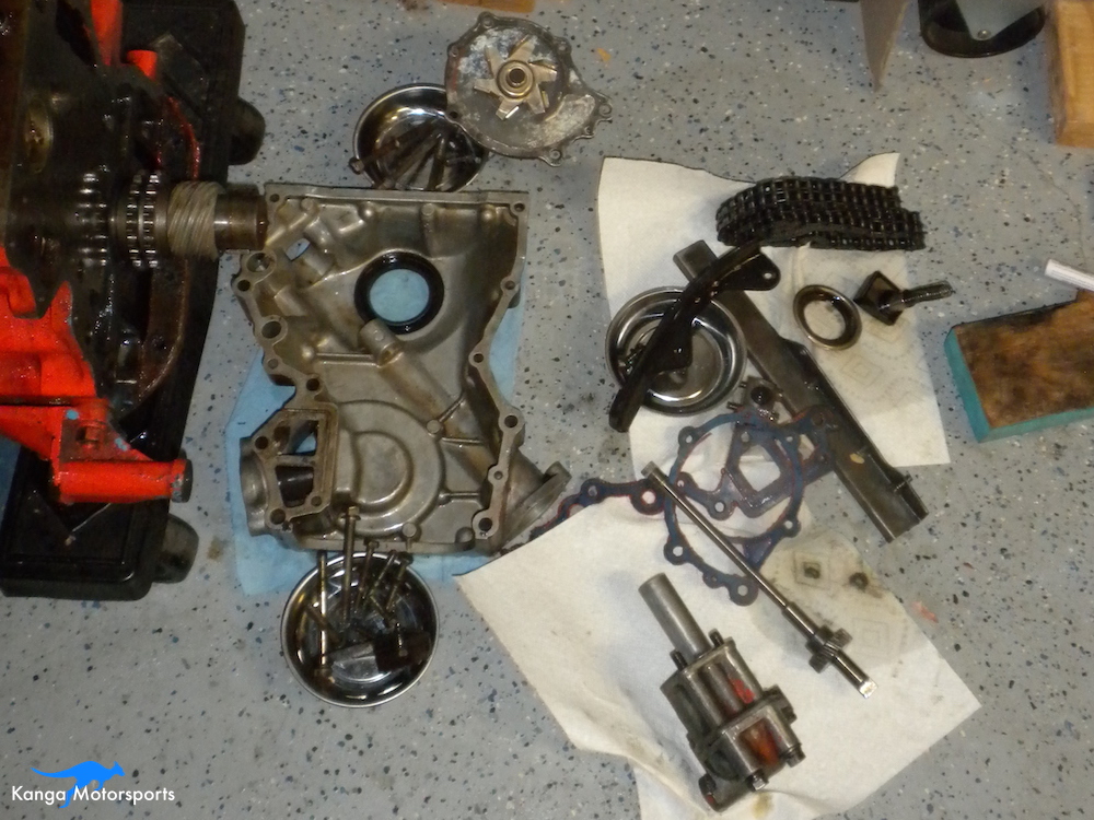
The oil pump and distributor drive can then slide out. Remove all the front cover bolts using a 12mm socket and ratchet. Next remove the chain, chain guides, oil slinger and tensioner.
I also take photos as I go so I remember where everything goes and more importantly can check the orientation. Plus memory is pretty cheap nowadays so snap away.

Connect the engine cradle from the engine stand to the back of the motor. Adjust the arms to the right spacing and use four M10 x 1.5 x 70mm bolts and M10 washers as spacers. Tighten the bolts using a 17mm socket and ratchet. Connect the motor to the lifting gear you can use bolts connected to the engine block.
Be very careful the engine block is heavy. Just in case don't put any part of your body underneath the engine. Using an engine hoist, or a couple of burly blokes, you can now lift the engine into the air and guide it onto the engine stand. A friend can be helpful to help guide and orientate the cradle into the engine stand. Slide the retaining pin into the engine stand and place the turn over rod in place. Disconnect the engine from the engine hoist and remove the lifting gear from the block.
Remove the engine mounts from the side of the block. There are two bolts on either side that can be removed using a 14mm socket and ratchet. The passenger and driver side mounts are different shapes. Mark them or take photos to remember.

Use a 10mm socket and ratchet to remove all the oil pan bolts. Some are slightly longer than others. Bag and tag them. Remove the oil pan and oil pan reinforcement.

With the bolts removed you can now lift of the oil pan exposing the oil pick up and rod bolts. Remove the two oil pick up bolts with a 12mm socket and ratchet. Bag and label the oil pick up and bolts.

The front oil pump drive and chain gear is held on using woodruff keys. You should be able to slide off these gears but if they are stuck you can give them a very light tap with a rubber mallet or use a small block of 2x4 wood to help drive them off. Don't bang on them and damage the crank or make the situation worse. If they are really stuck you can also use a bearing puller to remove them.

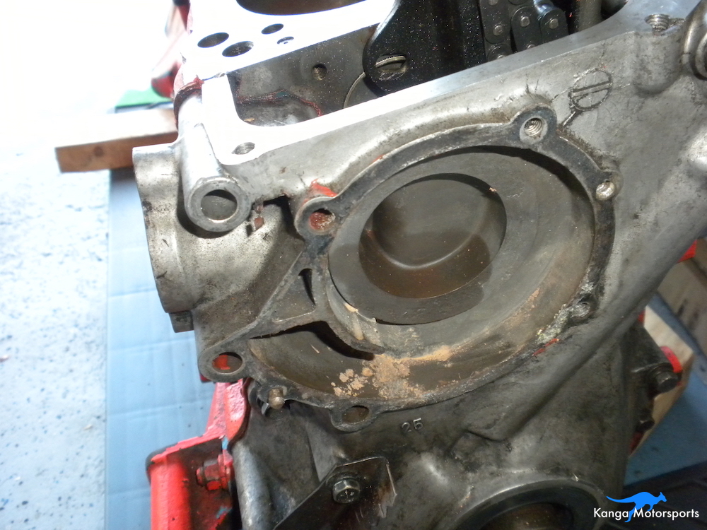
Place an oil drain pan below the motor. With the oil pan and pick up removed turn over the motor and let any left over oil or gunk drain out of the motor. To remove the core plugs use a screwdriver and hammer to drive one side of the plug into the block. The plug will rotate and you should be able grab the other end of it with channellocks or a vise grips. Be careful not to scratch any of the sealing surfaces. When the motor stops dripping you can turn it back over to access the rod caps and pistons.

Before removing the pistons and rods you want to measure the rod end play. Use a set of fine feeler gauges you will want to push the rod over to one side and then run various sizes of feeler gauges through the other side to determine the amount play. Record the gap for each piston and rod combination.
To remove the pistons use a 14mm socket, breaker bar and ratchet. Loosen the rod caps don't undo them all the way yet. You want to be careful that the piston doesn't drop out of the motor. Put your hand under the piston and hold it in place. Undo the rod studs and place rubber caps over the threads to prevent scratching the bores or crank. You should then be able to guide and push the piston out of the bores.

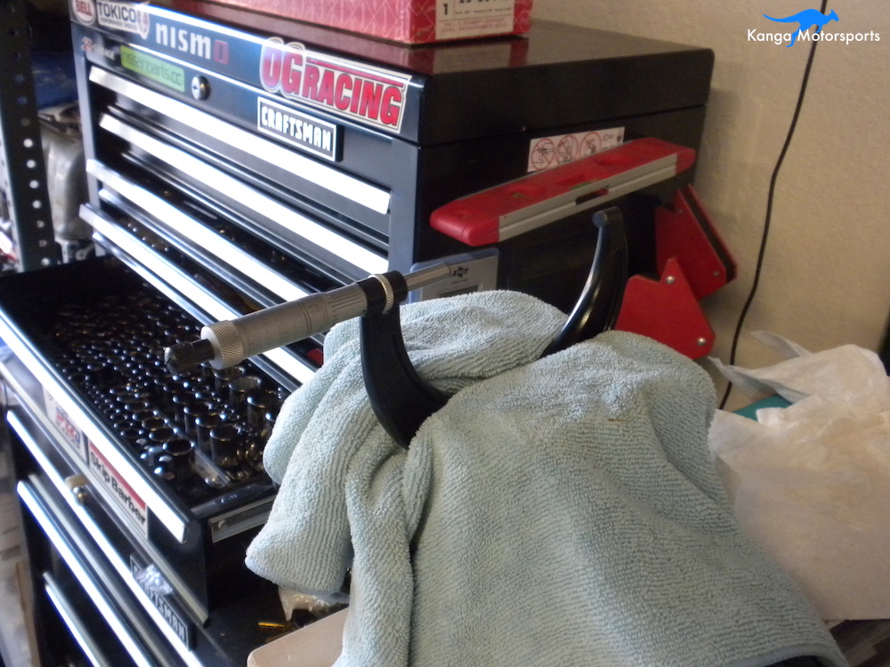
With the piston removed you can now measure the piston skirt using the 3-4 inch micrometer. Record the diameters for the pistons. If it is your first time using a micrometer practice a few times until you can get reliable and repeatable measurements. Record the values in your note book. Wear on the piston side can indicate excessive piston slap against the bores or poor oil pressure.

Continue with the remaining pistons removing them and recording their size. Inspect the rods, pistons and bearings for signs of wear or cracks. A few of the pistons had valve dents on the top, providing a clue on what led to this engines demise. It is always better to make the piston fly cuts yourself then have the engine do it for you.
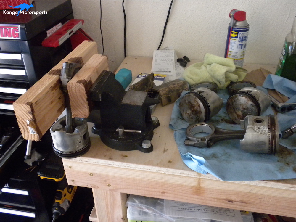
Using a couple of blocks of 2x4 wood hold the piston in a bench vise with the rod pointing up. Reposition the rod end cap and torque the fasteners down to 40 ft-lbs. You need to make sure you torque the rod caps correctly so you get good even bearing crush.

Measure the bearing using a 2-3 inch bore gauge. Record the value for each rod end. Use a 2-3 micrometer to set the zero on the bore gauge. Measure the rod bearings at 4 locations two diameters approximately 90 degrees apart, at both the front and rear of the bearing. If you haven't used a bore gauge before it will take a few goes for you to get the hang of it. Try a few times until you can get consistent repeatable measurements.

You can also weight each piston and rod combination. When it comes time for engine reassembly you want to weight each piston, piston pin, ring set and rod separately. Then balance both ends of the rod, piston and the assembly. Someone had coarsely balanced these rod and pistons by grinding the bottoms. While the assemblies might weigh the same they may have different weights at the piston and rod cap resulting in an uneven distribution of weight and possible imbalance.

With the pistons removed I was hoping that the crank would now turn over freely. Unfortunately this wasn't the case. If the crank spins freely now is the time to check the free end play. Connect a dial gauge to the magnetic base and mount it parallel to the crankshaft using the end of the engine block. Set the gauge to zero and rotate the crank to see how true it is in the main bores.
Next get a screwdriver or pry bar being very careful not to mar or scratch any surfaces press the crank all the way up against the main thrust bearing. Zero the dial gauge. Then move the crank all the way to the other side of the thrust bearing. Record the amount of big end play and compare against the Nissan specification.

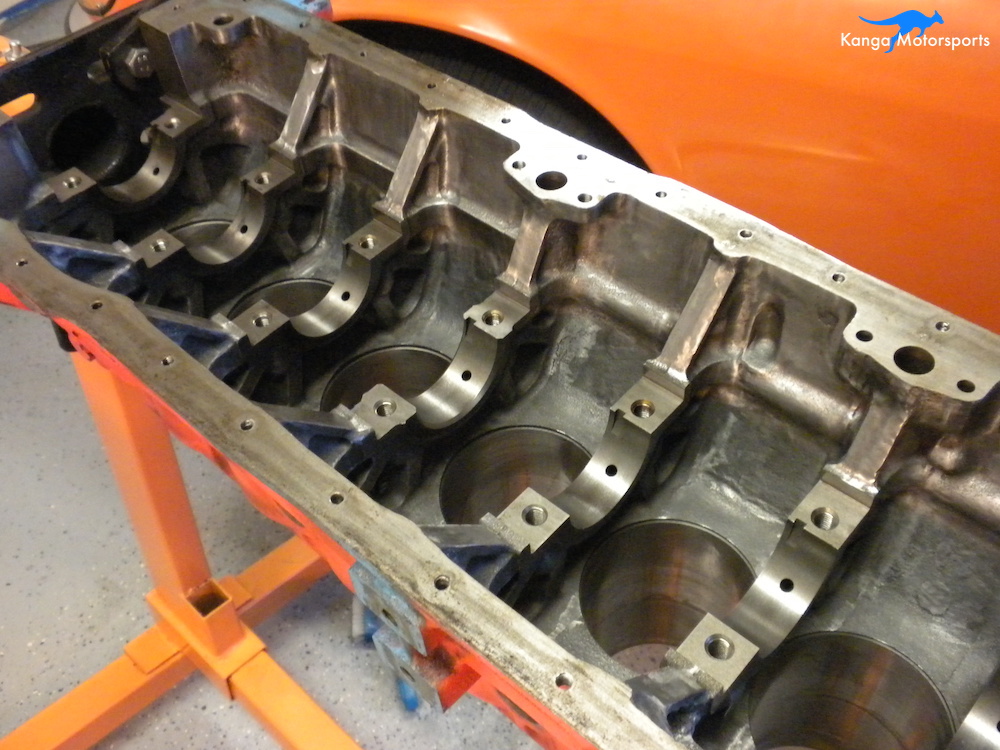
Time to inspect the main caps, bearings and crank. I mark the location and number of the main caps using a spring loaded center punch. You want to keep the main caps in the same position and not mix them up. Using a breaker bar and 17mm socket loosen the main cap bolts. Loosen in the order recommended by Nissan, starting in the middle and working outwards. Next you can remove the bearing caps. I started with number 6 because this looked to be where the block issue occurred but you can start anywhere.
The Ends can be particularly difficult to remove. They have a taped hole on top to help remove them. Thread in a bolt from the front cover, place a piece of 2x4 on the oil pan surface and use a pry against the wood and the bolt head. You might have to switch sides of the block to ensure the main cap doesn't get cocked and comes out straight.
You will need to remove the oil seals. They can't be reused but I like to keep them around so I can compare the new to old to make sure they are the right part.

As you are removing the main caps inspect them and and the bearings for any sign of wear or grooves. You can run your finger nail over the bearing and crank, if it catches it has a groove. If there is a groove on the bearing it needs to be replaced. Likely you are already replacing all bearings anyway. For the crank if there is a groove it needs to fixed by your machinist, it might polish out or need grinding down and oversized bearings.

With all the main caps out of the way the crank can now be removed from the block. Lift from both ends and directly up. The crank is heavy and you don't want to drop it or scratch any of the bearing surfaces.
Inspect all the journals looking for scratches or grooves. Use 2-3 and 3-4 inch micrometers to measure the rod and main bearing surfaces on the crank. Measure the rod bearings at 4 different locations two diameters approximately 90 degrees part, at both the front and rear of the journals. The crank will have little radiuses at the end of the pin surfaces measure slightly in from these or you can get bad results.
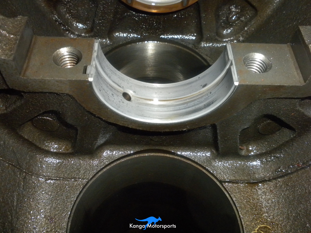
Inspect the lower half of the main bearings. Uneven wear might indicate corresponding issues on the crank.

Re-install the main caps and torque to 40 ft-lb (5.5 kg.m) in the recommend Nissan order. Using a 2-3 inch bore gauge measure all the bearing diameters at the same 4 locations, 2 diameters at 90 degrees apart, both front and back. You want to avoid the oil grooves and half shell seams. Zero the bore gauge using 2-3 inch micrometer, set at the expected values and then use the dial to check the difference. Record the values as you go. To gain access to each of the main bearing you will have to remove previous main caps as you go.

Next you can check the bearing crush. Most of my bearings were worn and the block spun a bearing in number 6 main, I was going to get new bearings anyway, so I decided not to check crush.
Remove the bearing shells from the mains and main caps. Re-install the main caps and torque to 40 ft-lbs (5.5 kg.m). Then repeat your measurements for the main surfaces, recording as you go.

Again you will have to remove the main caps as you go to have access to subsequent main surfaces.

With the engine disassembled; pistons, rods, crank and main caps removed you can measure the cylinder bores. Since some of the pistons were low in the bores there was light surface rust on the exposed bores. The other bores were great with the cross hatching still present.
Measure the cylinders bores at 6 different locations. You want to measure for taper in the length of the bore and any ovaling in the piston movement direction. Measure 2 opposing diameters at 3 different heights in the bore. The diameters should be perpendicular one in the long direction of the block and one in the rod motion direction. The heights should be towards the upper, middle and lower area of the bore.

Use a 3-4 inch micrometer to zero the bore gauge. If you are getting weird results in the bore, rotate the bore gauge slightly and check the local area for consistency. Sometimes the surface rust or a gouge in the bore can throw off the results. Like before you can run you fingernail in the bore to check. Record the values as you go.
Before you check the block deck for flatness you need to remove any dirt, grime, oil or other build up on the surface. Use a gasket scrapped if there is gasket residue. To do a final clean on the deck use a razor blade perpendicular to the surface and run it all over the surface in a gliding motion. The razor blade might lose sharpness over time, so I use a fresh blade to do the final clean. Be extremely careful not to mar or gouge the deck surface with either the gasket scrapper or razor blades. The goal is to remove any build up, not dig a new surface.

Measure the block deck flatness at multiple locations, use a note pad and pen to record your measurements as you go. Lay the straight edge across the cylinder head lengthwise. You want to place it at the front, middle and back of the head. Then also do the diagonals from each corner to the opposing corner do both diagonals. For each placement of the straight edge use the fine feeler gauges and attempt to slide them between the straight edge and the head surface. Try different size feeler gauges and determine the locations and height of any flatness variations. The maximum Nissan specification is 0.10mm (0.0039 inches) any pockets larger than that and you have to have the block decked.

In the next article we clean up the internals of the engine block and begin the modification process before sending it off to the machine shop.
Want more Datsun 240z articles and tech tips sign up for our Kanga Motorsports Newsletter
Other Datsun Engine Build Articles