
Now the cylinder head is clean you can start making performance modifications. A big area for improvement on the L-series head is modifying the intake and exhausts ports. Don't go crazy hogging them out and making them huge. Here is a step-by-step guide for porting and polishing the ports.
Cylinder head work done up to this point:

Tools and Equipment Needed:
Air Compressor
Straight Die Grinder - Ingersoll Rand 307B
90 Degree Die Grinder - Ingersoll Rand 301B
1/4 inch Mandrels
80 and 120 Grit Sanding Scrolls - Harbor Freight PN: 62394
1/4 inch Carbide Burrs - Astro 2181 Double Cut Carbide Burr Set
Dremel with Flex Shaft
80 Grit Thin and Thick Flap wheels - Dremel PN: 502 and 504
120 Grit Thin and Thick Flap wheels - Dremel PN: 503 and 505
180 (dark brown) & 280 (light brown) Grit Finishing Buffs - Dremel PN: 511E
320 Grit Finishing Buff - Dremel PN: 512E
3/4 inch 3M Radial Bristle Discs
Blue 400 Grit
Pink 600 Grit
3M Radial Bristle Disc Mandrels
Felt Polishing Wheels - Dremel PN: 414
White Rouge
Tap Magic or WD40
HD Pro Simple Green
N42 Intake/Exhaust Gasket - Nissan PN: 14035-E4610
Measuring Calipers
Machinist Die or Sharpies
Painters Tape
Gloves
Safety Goggles
Particle Filter Respirator Mask
Microfiber Towel
Bright LED Lights

Cylinder Head Porting:
Before you attempt porting you should read up about what you are trying to achieve and watch a few videos. I also recommend using your tools on a similar material so you can get a feel for the amount that is removed with each pass based on revolution speed, pressure and contact duration. If you don't have spare material around you can always try cosmetic clean up on the exterior casting.
Grinding and sanding will produce a lot of fine metallic particles and dust, make sure you have proper safety equipment; safety goggles, gloves and a particle filter respirator mask. You will be amazed how filthy and dirty the bench, surrounding area and even garage gets.
Planning
Before you get started you want to come up with a plan. Don't jump right in and start grinding away with carbide burrs. You are likely to ruin the head by hitting a water passage or worse.
I spent a fair amount of time reading the following books:
Theory and Practice of Cylinder Head Modification - David Vizard
Hybridz also has a lot great information
I took notes as I went and then condensed them down into actionable items I could undertake. Then I made a second list for items to be done at the machine shop.
Here is my list of work prior to the machine shop:
Match the intake and exhaust ports to the intake and exhaust
Clean up the course casting flash
Clean up and smooth the transitions in the bowl area
Short side radius
Long side radius
Bowl to seat transition
Clean up and smooth the transitions in port area
Clean up and smooth the transitions around the valve guide
Even out and finish the intake ports to a 120 grit finish
Even out the exhaust ports to a 600 grit finish
Polish the exhaust ports
Sounds like a short and simple list. This project took me a very long time with several hours spent at each step across all the ports. Lets get started.
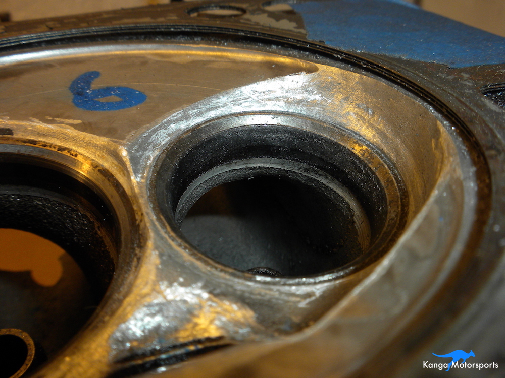
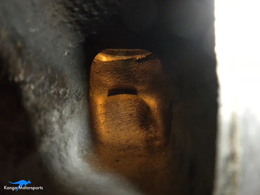
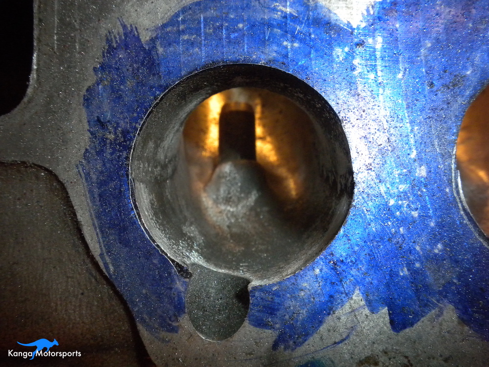
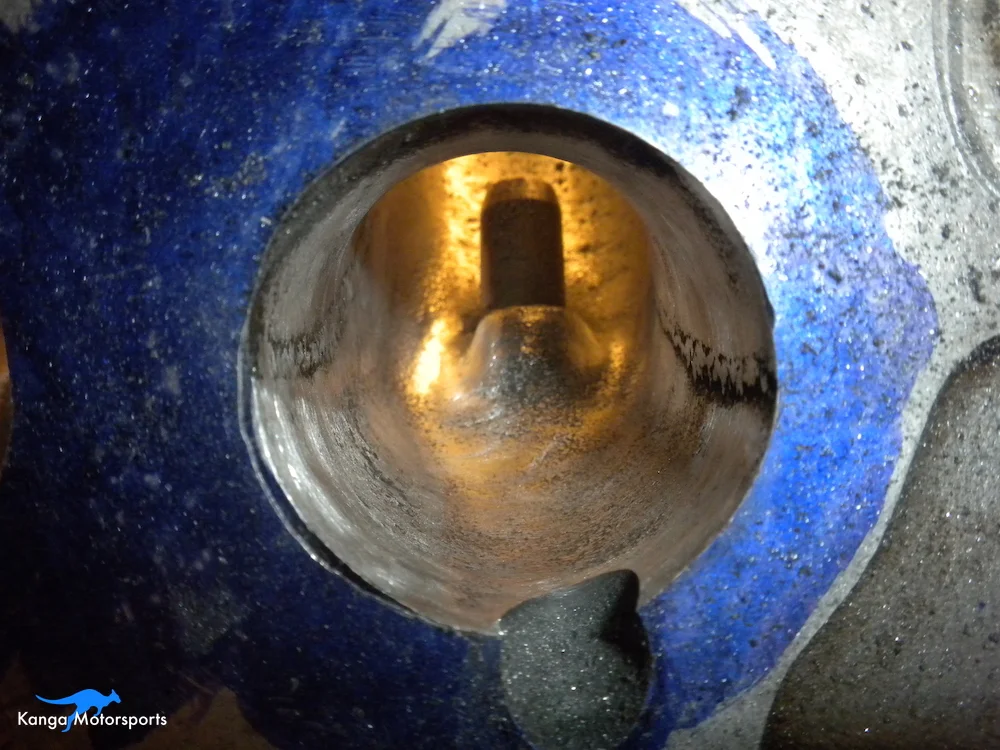
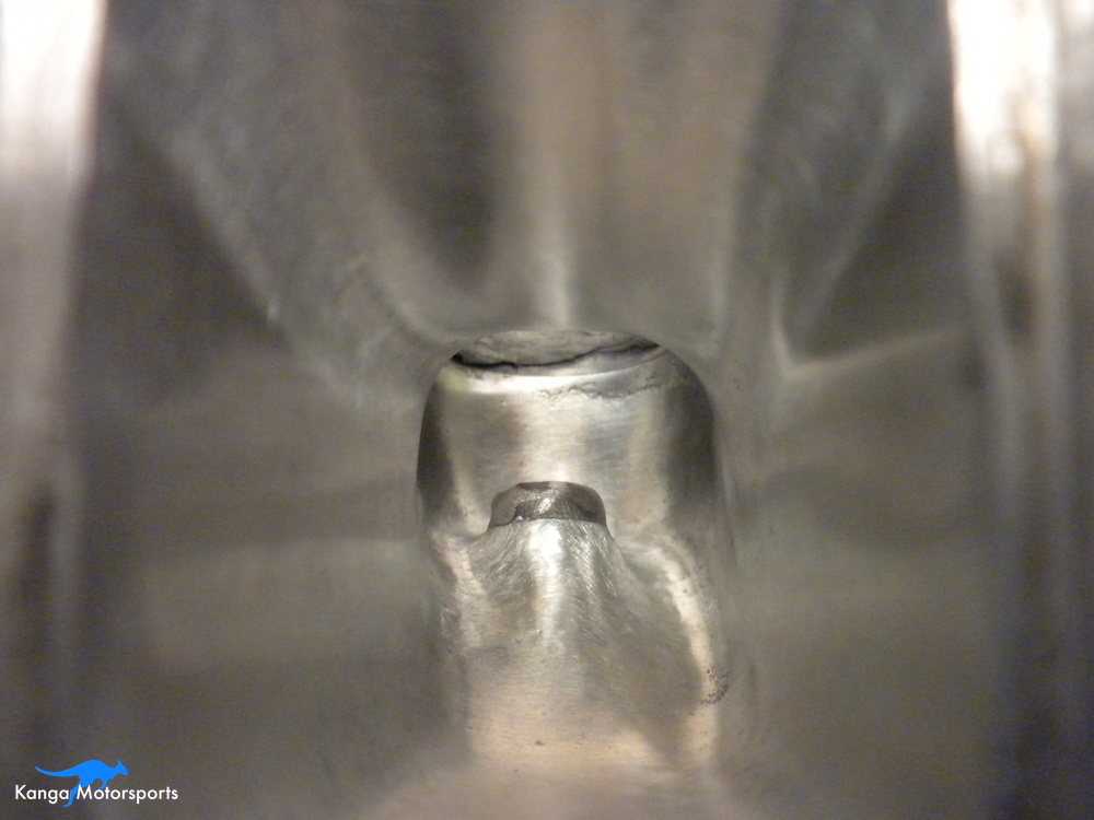
Cylinder Head Issues
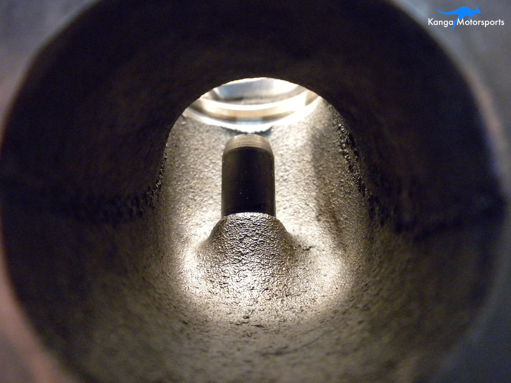
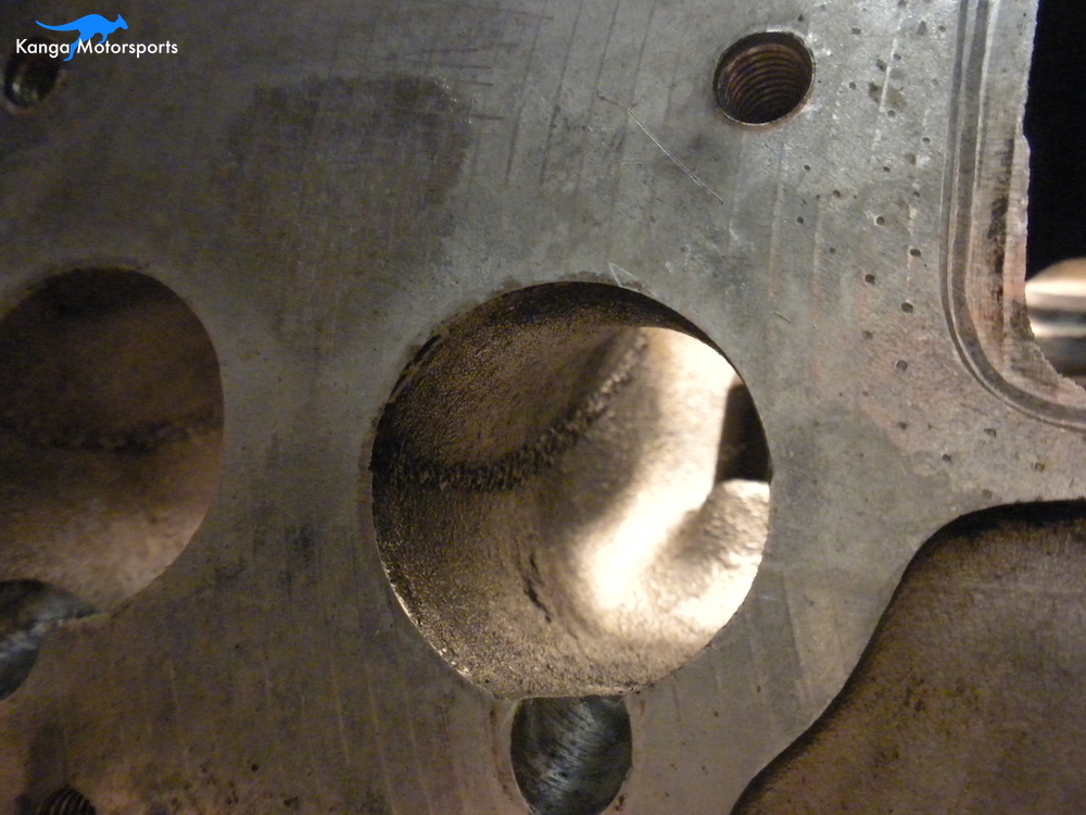
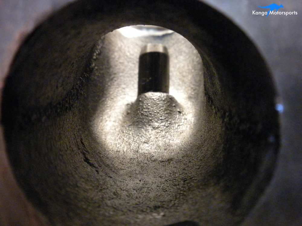
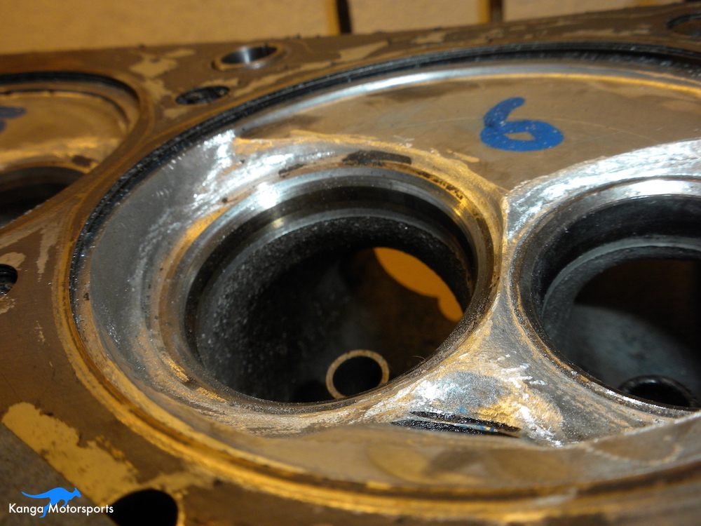
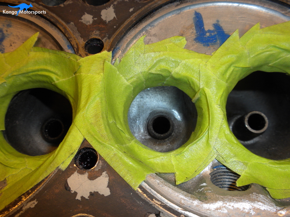
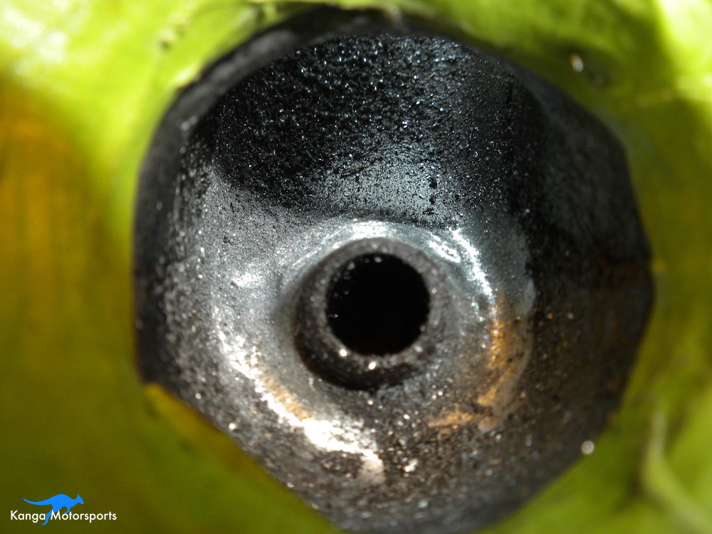
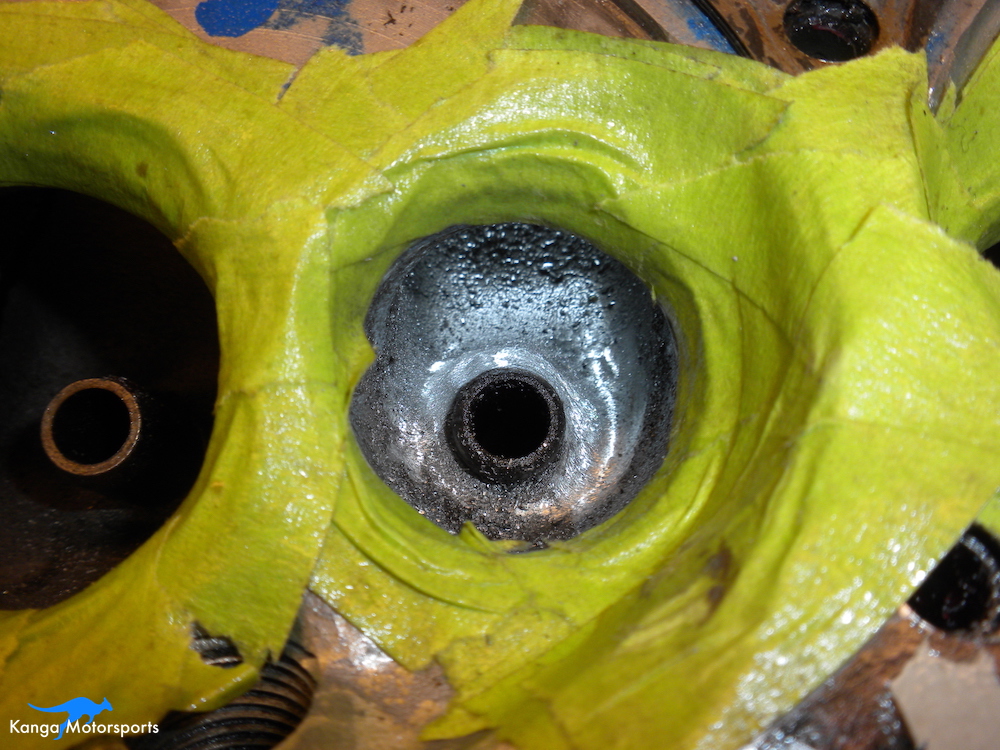
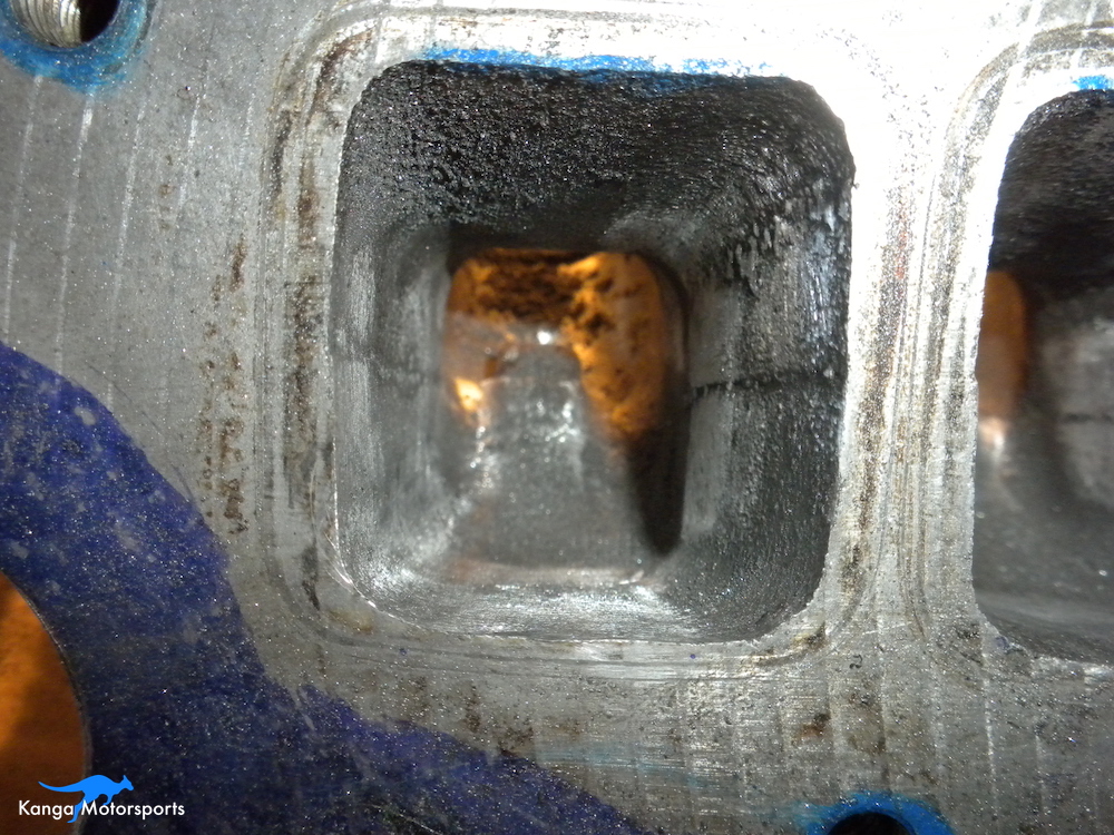
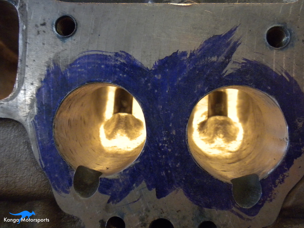
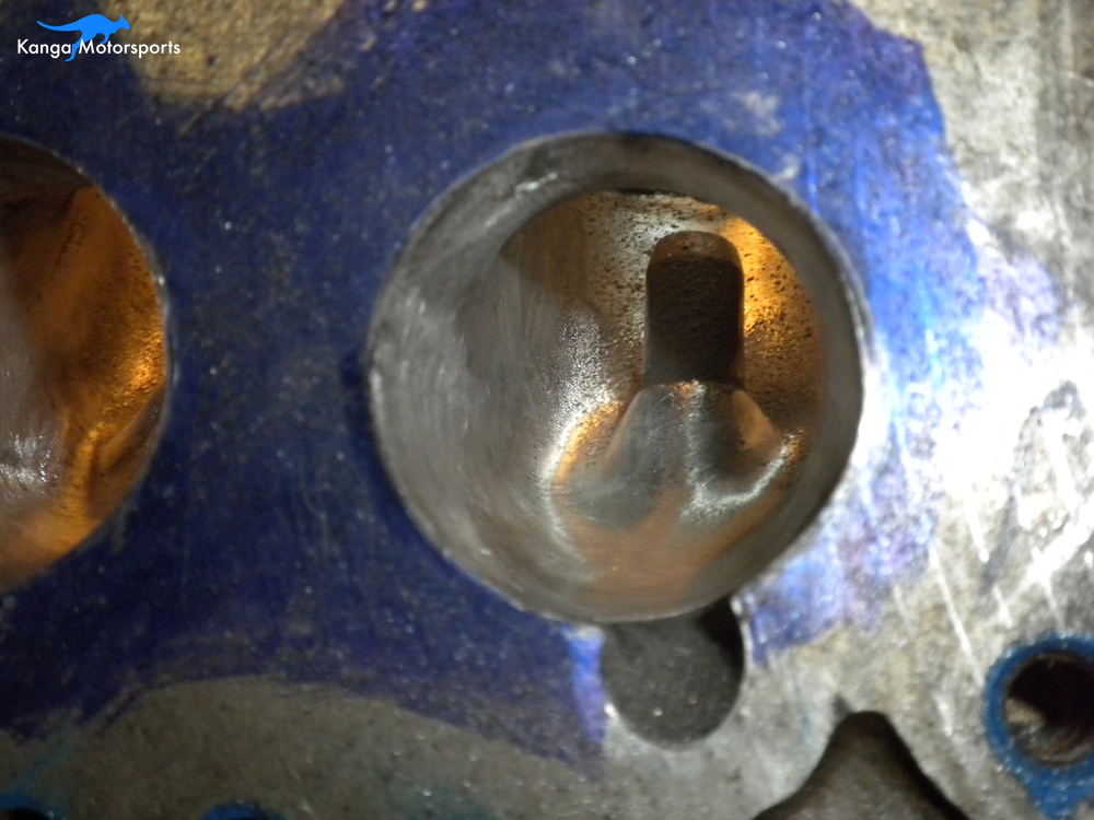
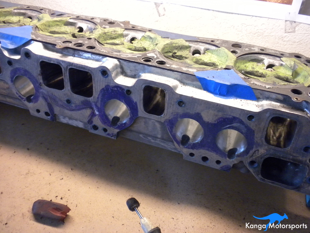
When the head is cast there can be shifts in the mold or casting sand that result in irregularities and defects. The casting process can produce small voids and leave an overall rough surface. On most ports you can see a casting line where the two halves of the mold met. The transition from the port to the valve seat can include steps, voids or extra material (casting flash). The short side radius can be a big problem, run your finger around the area to feel any jagged areas you might not be able to see. All these issues can result in poor flow and hurt overall engine performance. You can see many of these issues in the before pictures.
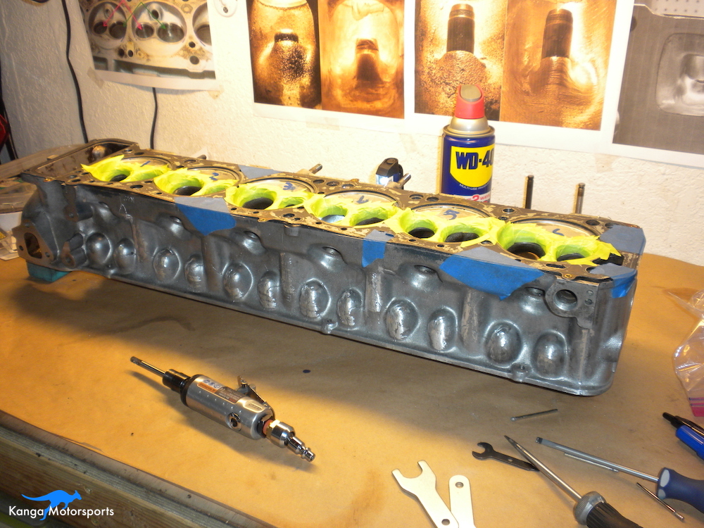
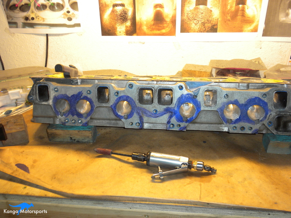
Tools and Marking
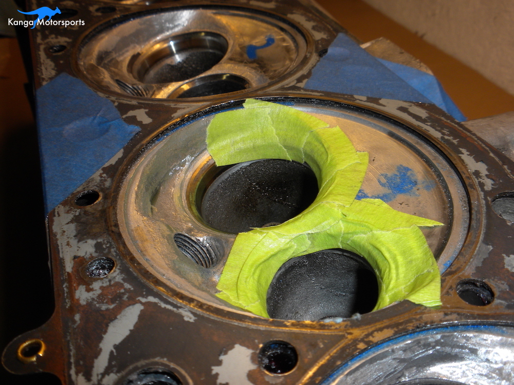
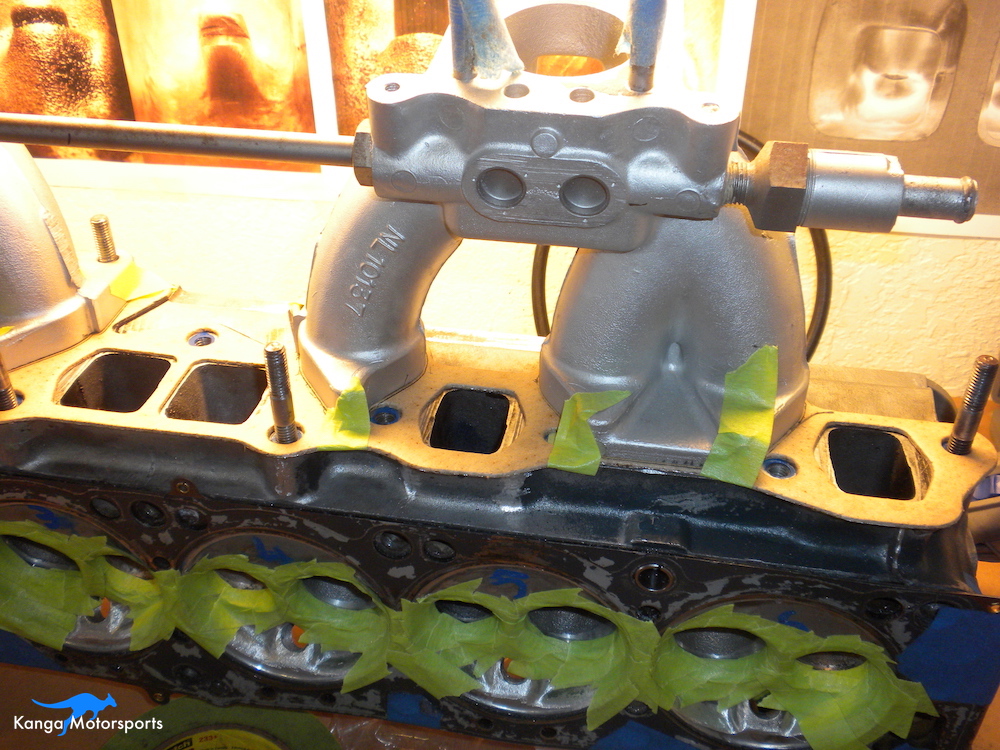
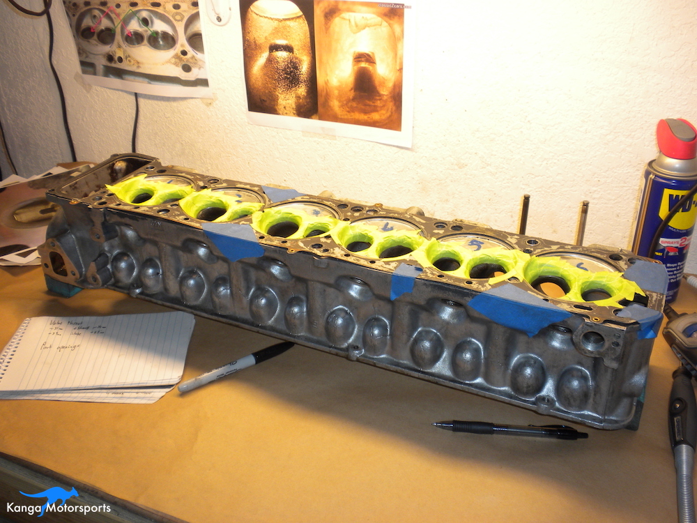
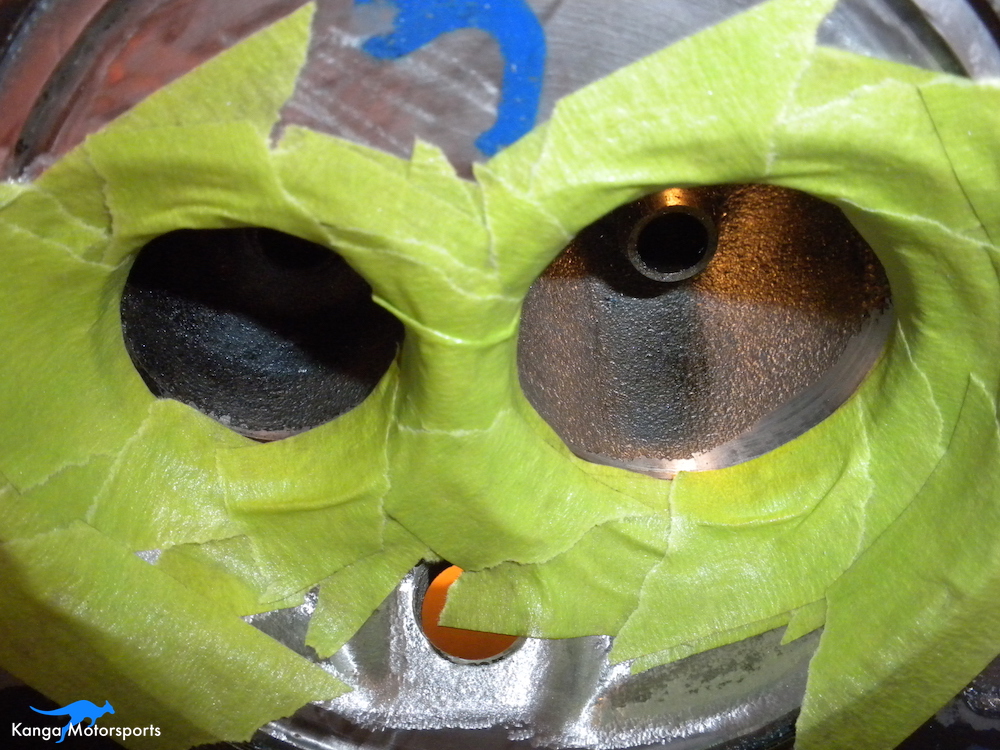
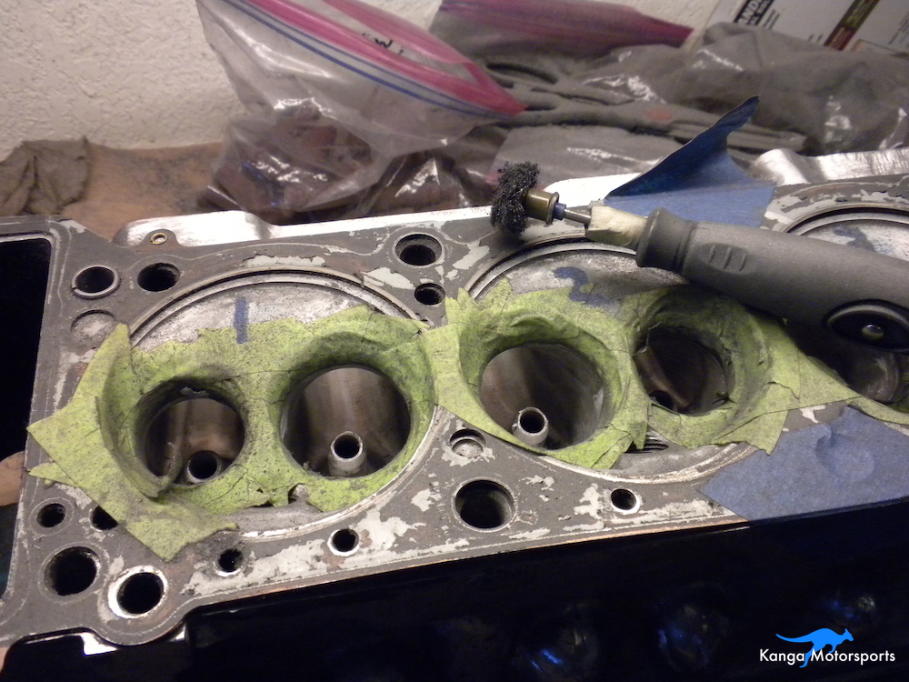
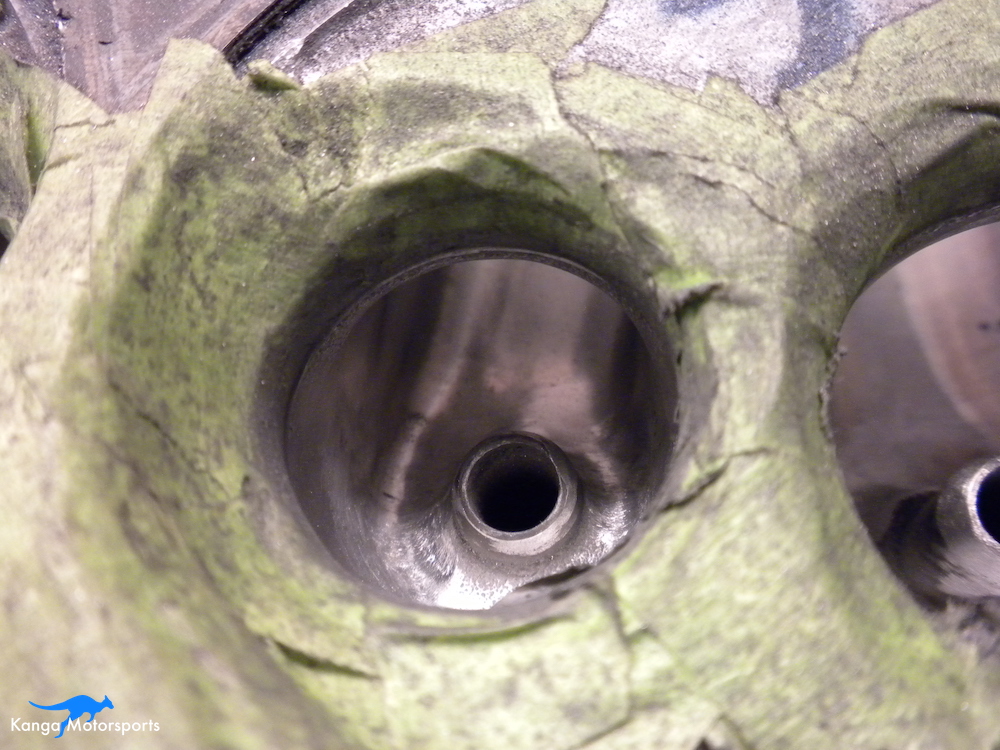
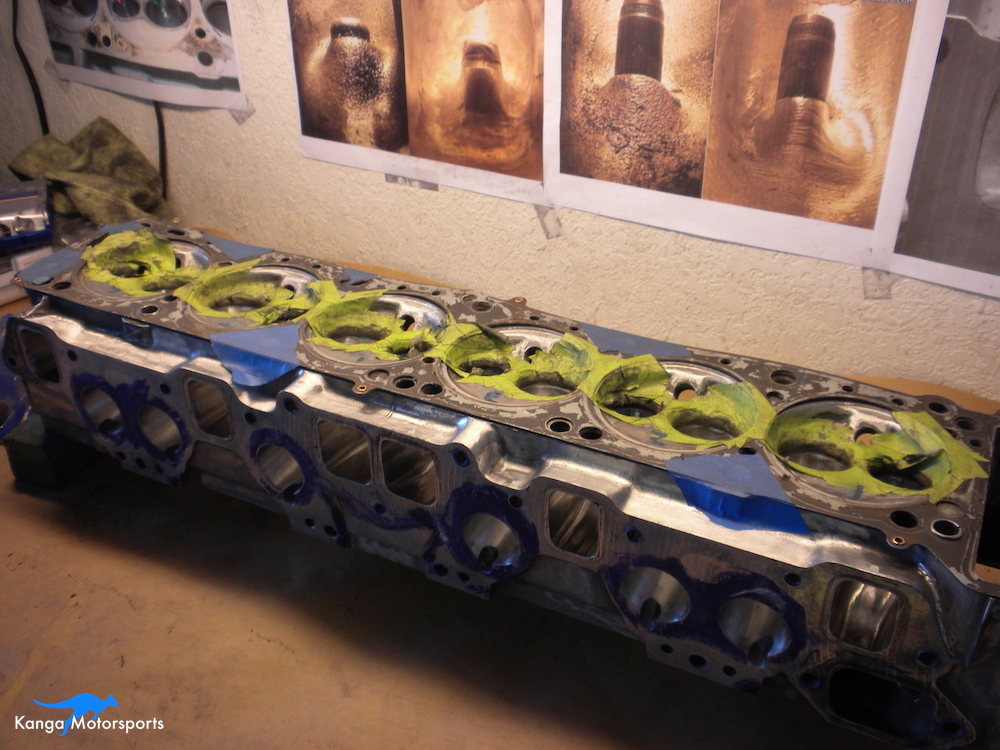
Before you start removing material, protect any areas you don't want to accidentally bugger up. When doing the bowls you want to be extra careful. Namely you are worried about the valve seats. I used multiple layers of painters tape on and around the valve seats. If I hit them with a sanding scroll or carbide burr the hope was I would have a little protection before I start cutting into the seat. You will slip, you will make a mistake, so you want to minimize the size and magnitude of the mistake when you do.
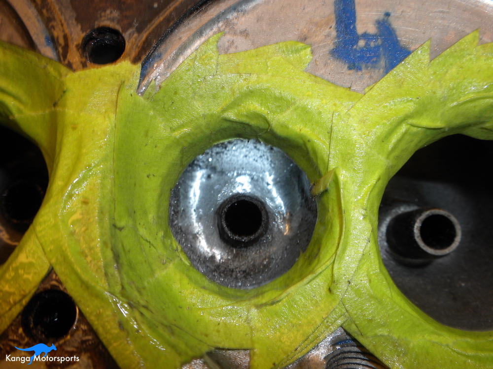
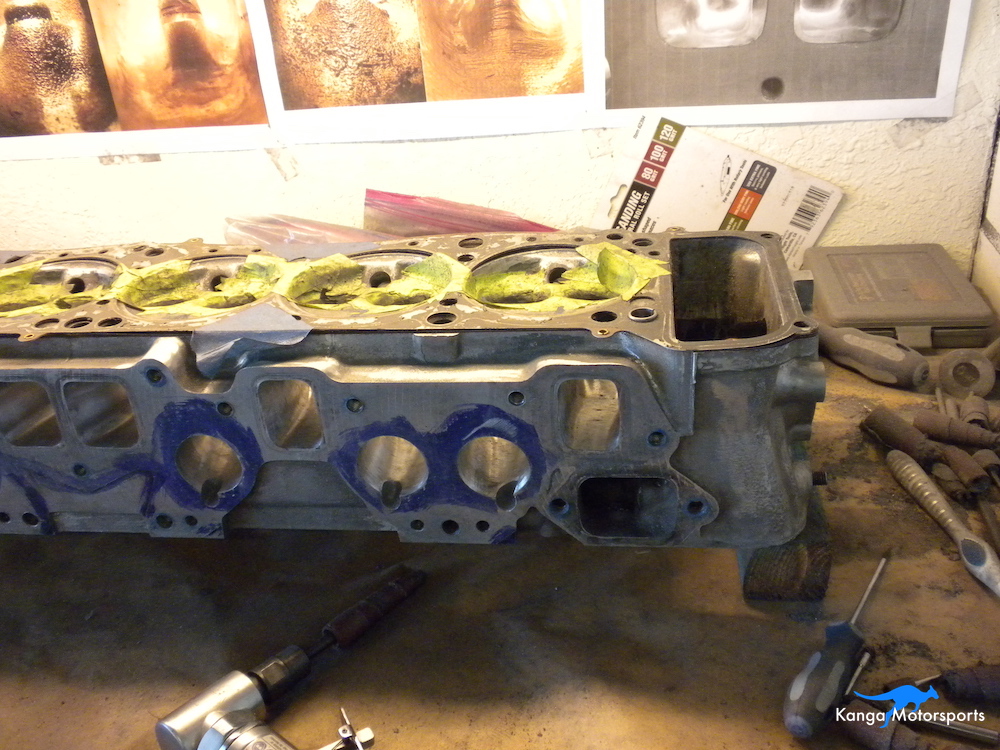
Mark up the intake and exhaust ports by scribing the areas to remove. I use a combination of sharpies and machinist dye. I found the sharpies are good if you need to just quickly mark a spot but it will rub off easily. I recommend using the dye and scribes as it lasts longer and is easier to see when the dust starts flowing.
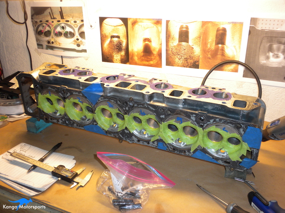
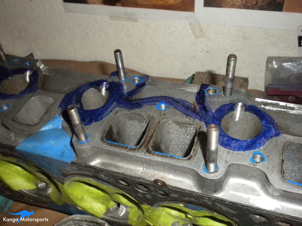
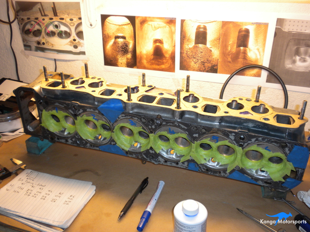
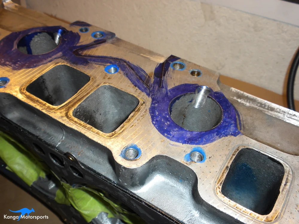
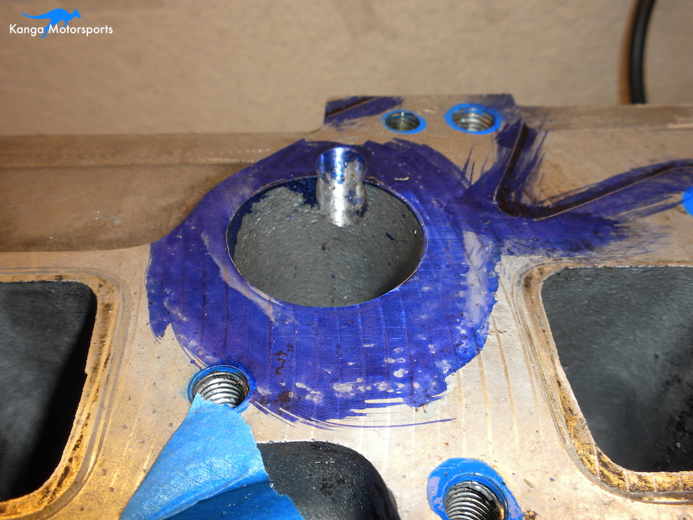
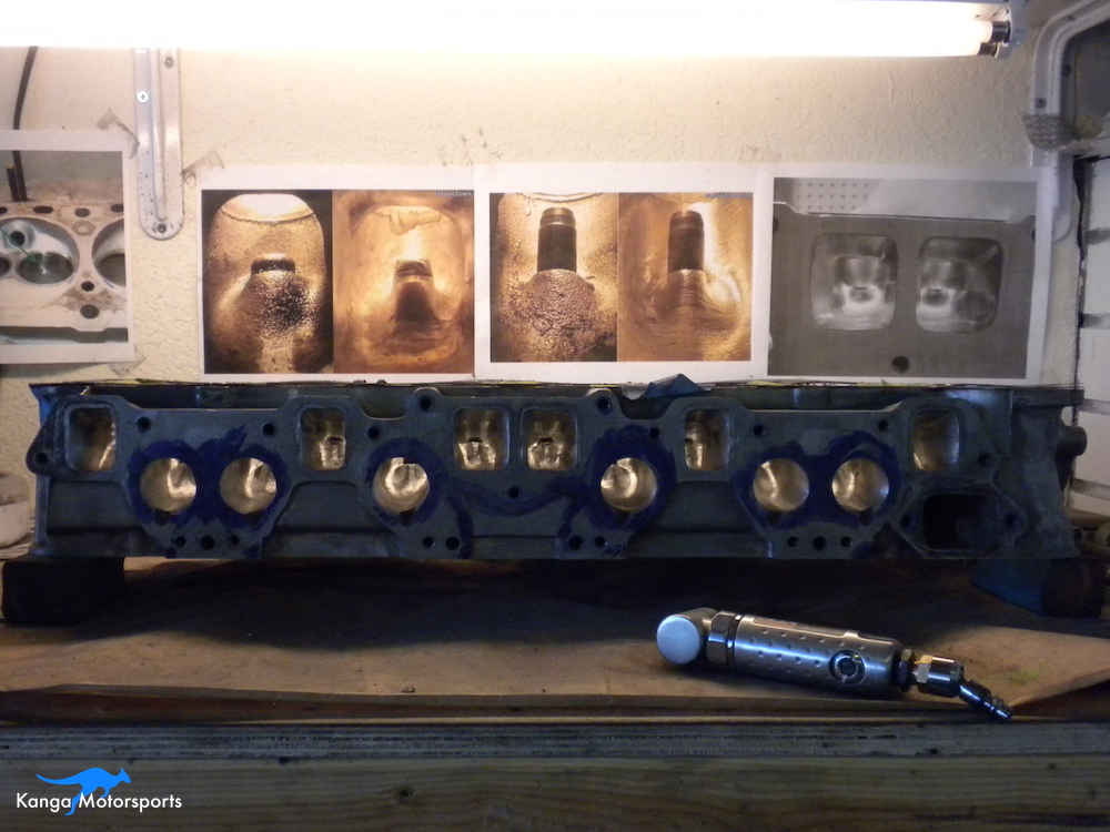
Paint the machinist dye on the intake and exhaust face and then insert the head studs. When the dye is dry, place the intake and exhaust gasket on the head and mark the position. You can then mark up the intake and exhaust port maximum sizes. This gives you the largest size possible not the size you want. The gasket helps but it doesn't define the port size.
Next place the actual intake you are using and mark the location on the head to make it repeatable. Look down the intake using a bright light and mark any protrusions into the port flow area. You may have to take the intake off and on a few times to double check.
Double check the size of each of the ports by measuring with dial calipers, making sure the markings will make the ports evenly sized.
Coarse Cut with Carbide Burrs
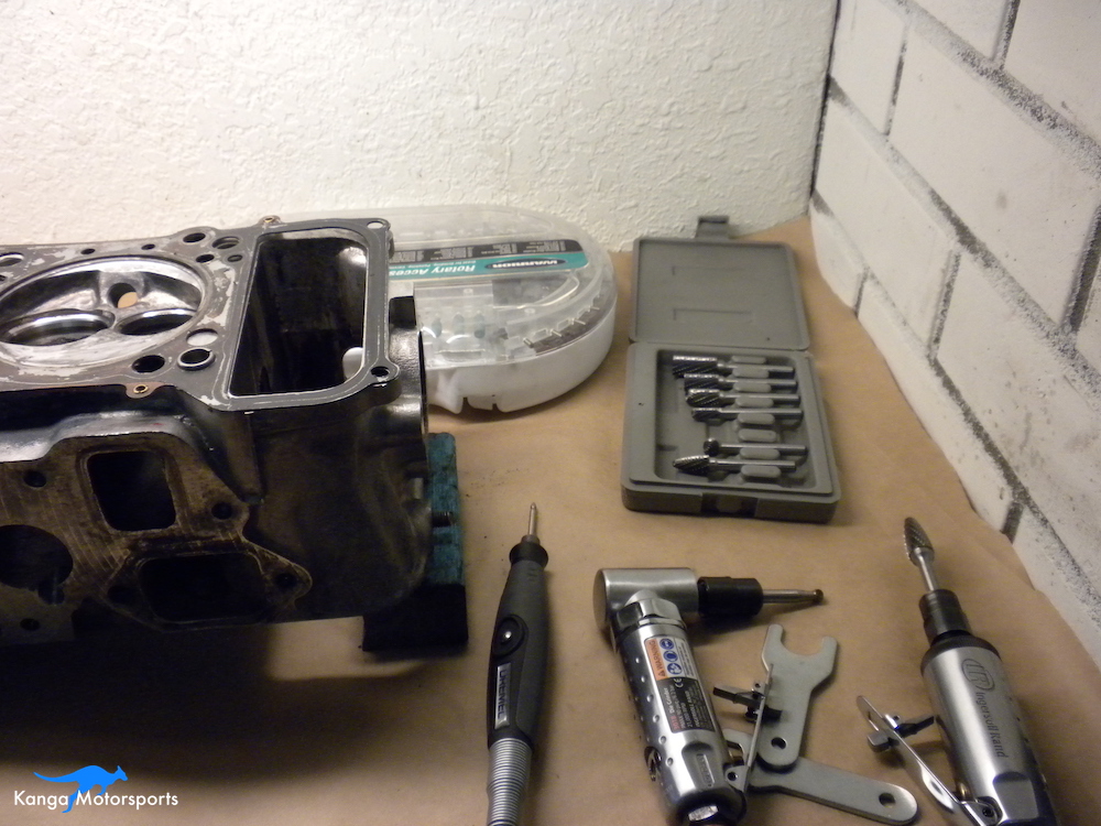
I use two different die grinders, one is straight the other is a 90 degree unit. Access and the area being worked on, determines which one to use based on control, reach and comfort. Be careful, the die grinder and carbide burr can skip or runaway on you. Position your hands to minimize any runaway. Use your other hand to help support the tool hand and hold it steady. You will have to reposition yourself and the head several times to be in the right orientation and the needed direction for the work flow of the tool.
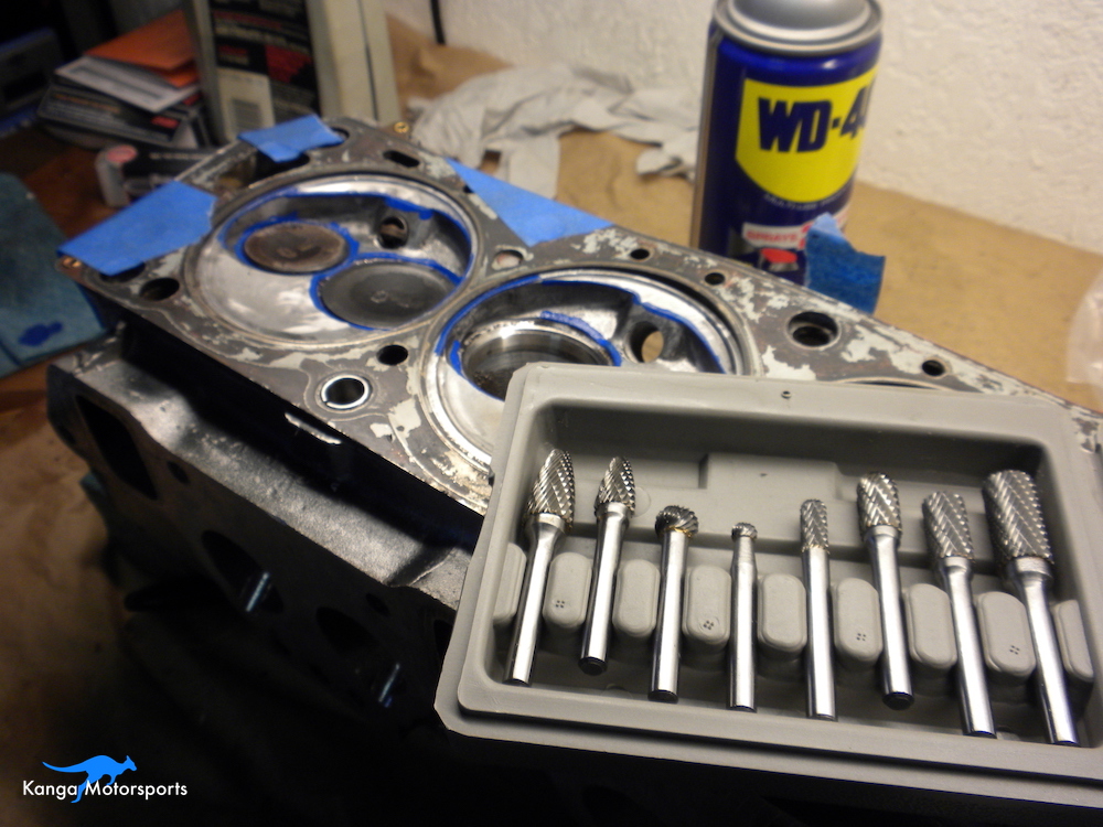
Cutting fluid like Tap Magic can prolong the life of cutting tools and also make the cuts easier. Sometimes the tool will skip if you are not at the right angle or moving in the wrong direction. The cutting fluid also seems to give you a little more leeway.
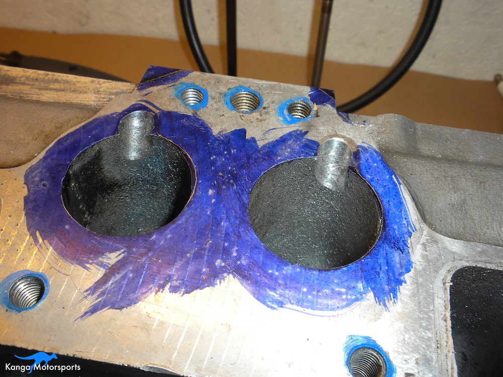
Start in the bowl area using carbide burrs to remove material and smooth the port, around the valve guide and bowl area transitions. Carbides can remove a lot of material very fast so if you haven't used them before you should practice on the exterior or spare material. Once you get the hang of it, then start working in the bowl area.
The carbide provides a coarse cut. Don't cut all the way with the carbide burrs, leave some material behind as you will fine tune the shape with sanding scrolls and higher grit flap wheels and buffs. Do both the intake and exhaust ports. The intake ports are large and so a little easier to work on, a good place to start. You want to remove an even amount of material from each port. You can do this by measuring and inspecting each of the ports.
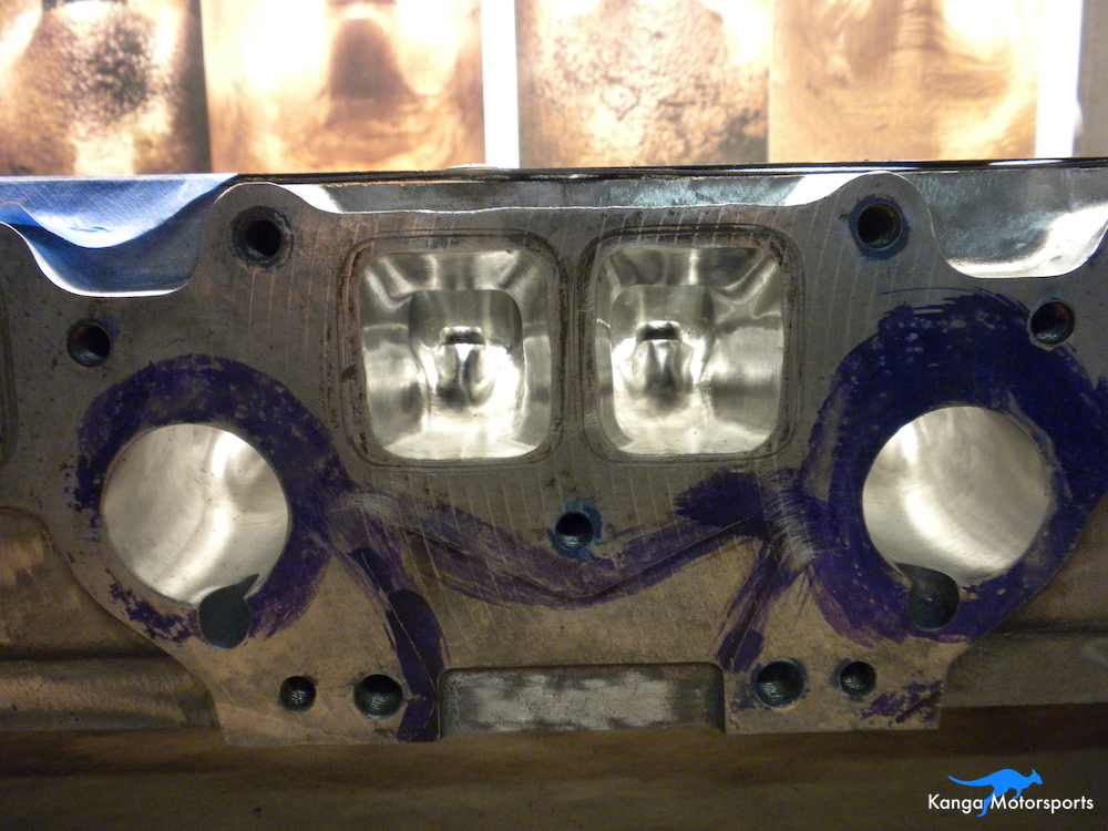
I like to start in one of each type of port and try to perfect the coarse cut and shape. Then I can move down the head replicating all the ports as I go. The different shapes of burrs have their different uses. The small and large balls, rounded cylinder and flame can be used to shape, contour and smooth the edges and flow. The straighter edged burrs can be used smooth out the transitions and intake/exhaust port openings.
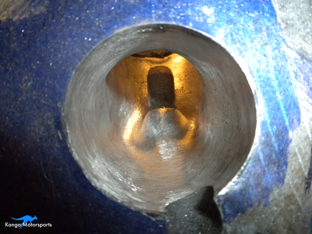
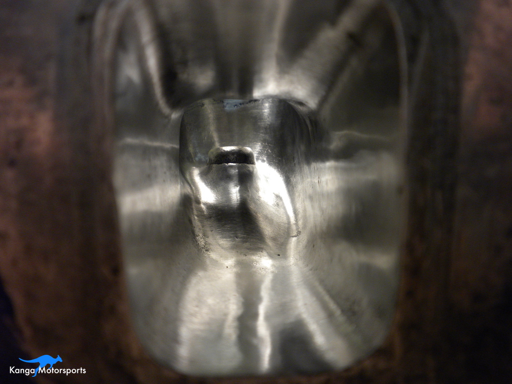
Use the smaller and thinner carbide burrs to smooth out the finish on the bowl areas. Smooth out any steps or rough edges in the transition to the valve seat. The major work with the carbide burrs is to shape the material around the valve guides. The goal is to shape the port to allow the air to flow by having it follow as gradual a curve as possible into the combustion chamber. The pictures provide a guide for the shapes you are trying to achieve. The final cuts should smooth the overall finish and transitions from the port into the bowl area.
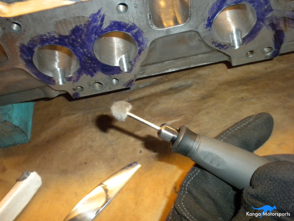
Shaping with Sanding Scrolls
Now that the course cutting is done with the carbide burrs you can switch over to sanding scrolls. I use two different die grinders a straight one for the main section of the port and a 90 degree one for the bowl and valve guide area.
There are also two types of sanding scrolls, straight cylinders and tapered cones. The tapered cones are my preferred type as they can get into the harder to reach areas and handle the complex shapes. The straight sanding cylinders are good for smoothing and evening out the runner area of the ports and matching the ports to the intake and exhaust. Experiment a little and see what tools and consumables works for you.
I started with the large areas of casting flash, knock this down and smooth out the surrounding area. Use the 80 grit sanding scrolls. The goal here is not to remove as much material as possible. The goal is to have a nice smooth tapering port all the way from the throttle plate to the bowl area. Remove the casting flash in both the runner and bowl area. Some ports will be worse than others and so might take more time.
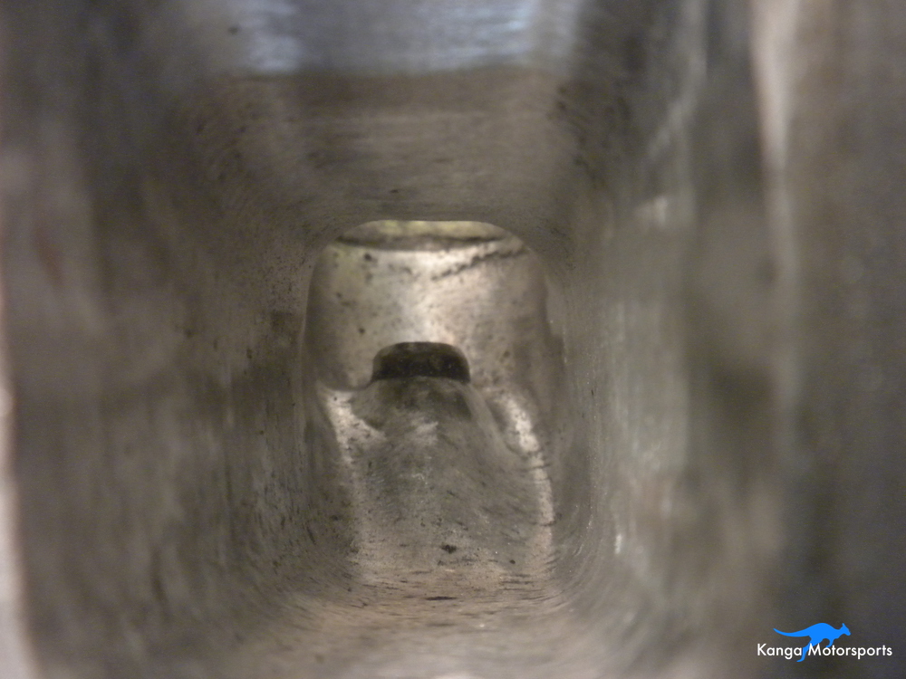
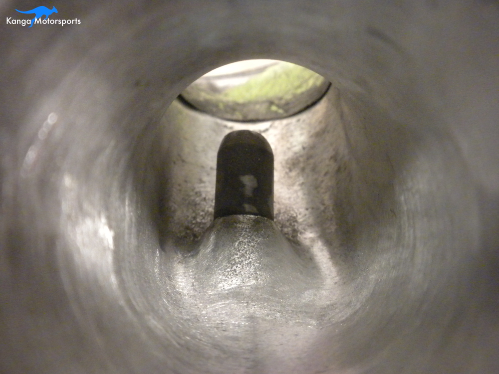
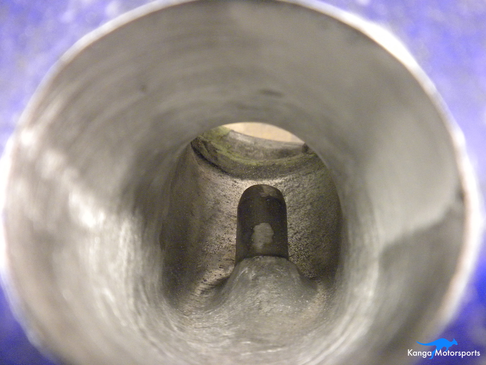
The sanding scrolls will help smooth out the coarse cuts from the carbide burrs in the bowl area and around the valve guide. Ensure there are no ridges from the valve seat to the bowl area. As you can see in the pictures you do not want to remove large amounts of material. You want to smooth the transition of the air flow from the port, around the valve guide, into the bowl area and through the valve seat. To do this you want smooth continues curves especially around the valve guide and into the bowl.
The sanding scrolls have a small diameter that is not suited to smoothing out the larger areas. Unless you are working on a specific feature you need to keep moving with the sanding scrolls or you will get small concave areas. Flap wheels have larger diameters and are better suited to achieving a more even finish on the larger areas such as the intake and exhaust port tracks. A good example of this is the casting flash in the ports. Once the large bumps are removed you can use the flap wheels to blend with the rest of the port. To use flap wheels you will need a flex shaft motor for the best access.
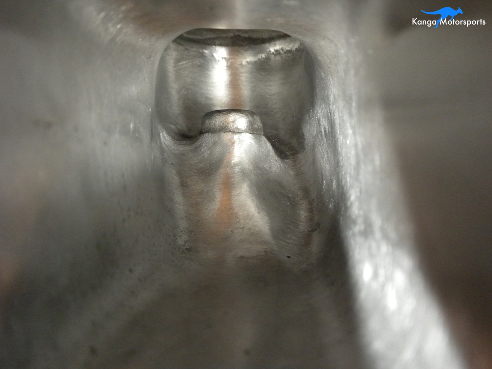
The short side radius occurs from the port floor all the way down to the valve seat. It is called the short side radius because it is the shorter distance the air travels into the valve seat. The short side radius should be a smooth continuous radius. It can be difficult to see all the features on the short side so you will need to use your finger and touch to feel the transition area and ensure your improvements. The thin flap wheels are excellent for working on the short side radius.
As the flap wheels get smaller in the diameter they are also well suited to working in the bowl area. The 80 grit can smooth out the rough cuts from the carbide burrs. The flap wheel can also further smooth out the transition all the way to the valve seat eliminating any further ridges.
Once complete, the 80 grit sanding scrolls and flap wheels should provide a smooth overall finish without the rough cuts or scratches. The surface will look dull and there will be some very light scratches.
Measure the ports you want to make sure they are evenly sized between the ports. Ensure you have removed enough material to match the intake and exhaust ports. You might have to reinstall the gasket, intake and exhaust to remark and check the ports as you fine tune their shape.
At this stage you can switch to the 120 grit sanding scrolls and flap wheels and repeat your work. Go over all the areas further smoothing out the transitions and eliminating any issues that would affect the flow.
The final finish from the 120 grit will provide a smoother surface with very light and fine scratches. It will look brighter than the 80 grit but not shiny or polished. Try to get a nice even finish all over. You can work in multiple directions to eliminate scratches that might be prevalent in the direction of the tool.
Depending on the quality of the head casting there might be pin holes or very small pockets that are recessed within the port. Do not remove large amounts of material to get rid of these pin holes or tiny pockets. This would cause large uneven bulges within the intake and exhaust ports. The affect on flow of these pin holes or tiny pockets will be far less then any bulges you might make or worse breaking through the water jacket. Some engine builders will weld on the head to fill these voids but that requires care and experience to avoid damaging or warping the head. I decided not to weld on the head for this build.
There is a lot of debate on the finish required for the intake ports. The general consensus for carbureted engines is that a slightly rough finish of 120 grit is desired to help the atomized fuel stay in the air. I don't know if this is true and I have not tested it to confirm. However, I decided to leave the intake ports with the slight surface roughness that is left behind by the 120 grit sanding scrolls and flap wheels.
Finishing Buffs
The goal of the exhaust port is to completely remove the combustion products. A smoother surface finish should provide for the best flow. I decided to continue to improve the exhaust ports with eventual goal of polishing them.
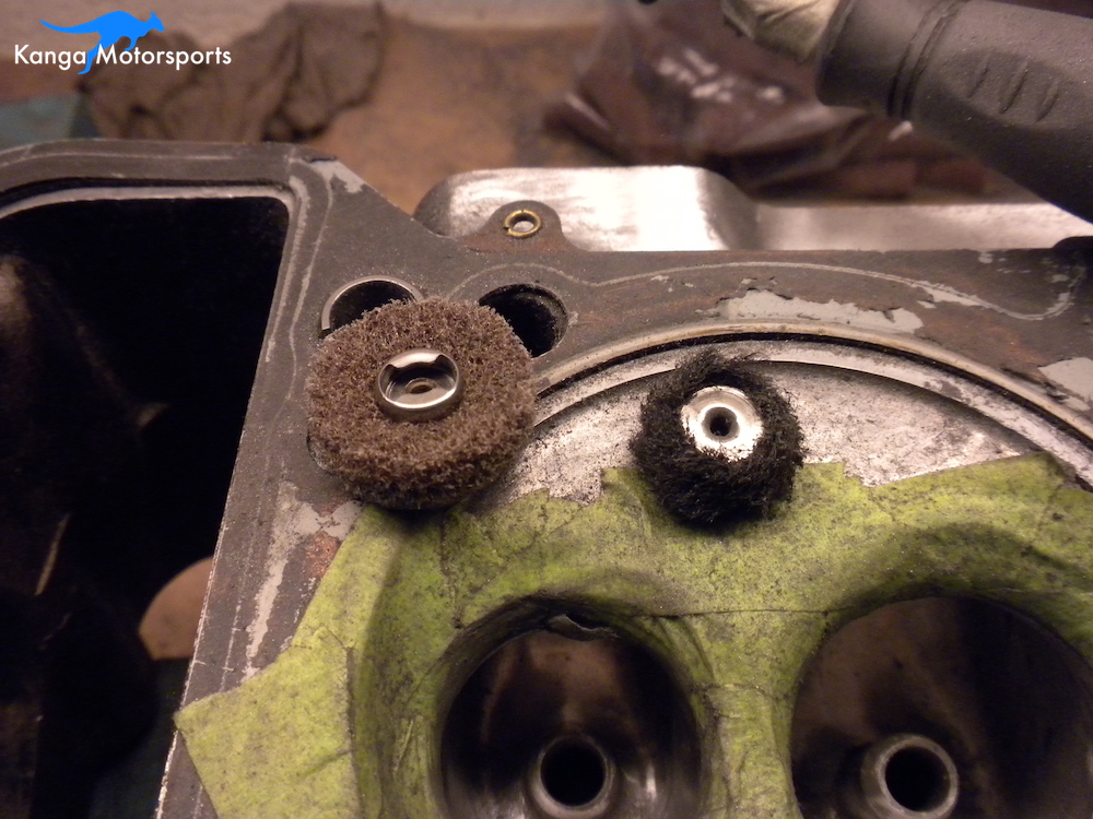
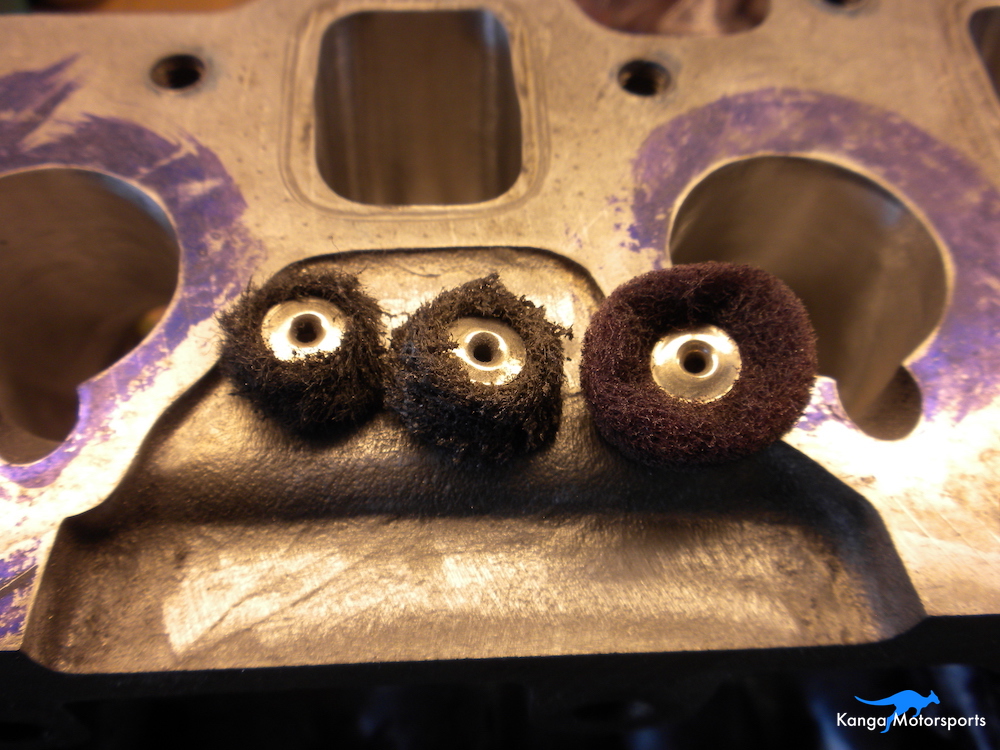
Sanding scrolls and flap wheels generally do not come in larger grits than 120. Dremel produces finishing buffs in 180, 220 and 320 grits. The buffs are soft and so can bend to the shapes within the ports. You do not have to press hard with the buffs, this will only result in them wearing out too quick. Over time the buffs will wear down with use, reducing in diameter. Start in the large port openings and then proceed into the bowl area followed by the value guide transition as the buffs wear down. I used about 2-3 buffs at each grit level to complete the ports. The intake ports are larger so you can use new buffs here and then as they get small use them in the exhaust ports.
You can use a Dremel, like I did, but I wouldn't recommend it. I burned through one porting a single head. Dremels are not really suited to this type of work, you want a high torque flex shaft motor like a Foredom.
Start with the 180 grit buff and go over all the previous areas from the sanding scrolls and flap wheels. To get the best finish work in a few different directions/angles to eliminate any scratches in the tool direction. If you have some stubborn scratches you might have to go back to the 120 grit. At this stage you should not be removing much material but instead working on the surface finish. Work until the finish is smooth and consistent before switching to the next higher grit. With successively higher grits the port should appear smoother and shinier.
3M Radial Bristle Discs
While you can make and there are some finishing buffs that go to higher grits they are not readily available. I decided to use 3M radial bristle discs as they come in appropriate small sizes and have a large selection of grits. You need a few grits greater than 320 to get a better finish prior to polishing.
The discs are mounted onto a mandrel, requiring a minimum of 3 discs and only operate in one rotational direction. The bristles on the discs have some flex allowing them to get into the tight spaces and contour to the curves within the ports. I used the Blue 400 grit followed by the Pink 600 grit to further refine the surface and produce a bright shiny finish.
Place the mandrel into the flex drive motor and use them as you did the flap wheels and finishing buffs. The final finish with the 600 grit discs should appear very smooth and shiny.
Polishing the Exhaust Ports
The final stage of completing the exhaust ports is to polish them. Since they are difficult to get into especially in the bowl area I use the small felt polishing wheels combined with white rouge.
Due to the small size of the wheels the surface is traveling fast so you want to make sure there is plenty of compound on the wheel. The white rouge will quickly turn black, it can also provide you a guide where you have already been. You will need to periodically add more compound.
A knife can be used to remove any excessive compound build up on the felt wheels and cut a new surface into the felt. The wheels will wear down and need to be replaced. Similar to the buffs use new wheels in the large port areas and worn down wheels in the tighter valve guide area. By using the front end of the wheel you can also taper it down to better access the compound curves. During and after polishing use a new clean microfiber towel to remove any excess polishing compound. It can be very difficult to remove some of the residual compound in the valve guide area. You can use brand new felt wheels to remove any stubborn left over.

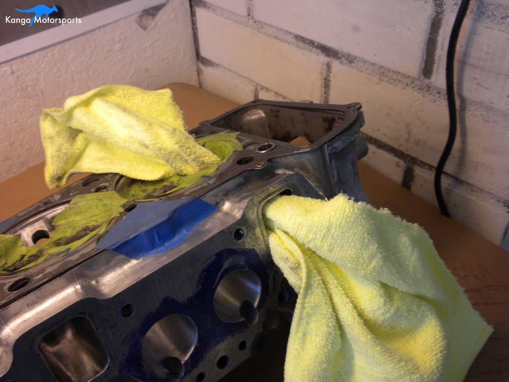
Stand back and admire your work. Now it is time to get the list together and get the head ready for the machine shop. Clean the head to remove any dust and grime from the porting process before taking it to the machine shop. I am assembling the head myself but you can have the machine shop do it. Here is the list I put together for the machine shop:
Deck
Cut new 5 angle valve seats and valves
Replace main oil gallery plugs with socket head plugs
Set the spring heights
Future articles we will cover the other head work still needed. Including:
Lapping the valves
Installing the valve oil seals
Installing valve, springs, hats and keepers
Installing the rockers and ensuring a good wipe pattern
Installing the camshaft
In the next article in the Datsun Engine Build series we port the intake manifold to match the intake ports of the cylinder head.
Want more articles on our Datsun Engine Build sign up for our Monthly Newsletter.
Other Datsun Engine Build Articles


